Commands
OpenPET utilizes a standard 32-bit wide Serial Peripheral Interface (SPI) to facilitate serial communications between any parent node and its children. The communication protocol follows a request-response architecture, where a parent node writes a command to a single child or multiple children and reads back the response. For a gentle introduction on OpenPET commands, see the Commands section in Getting Started.
OpenPET commands are 80-bits wide as shown in Fig. 52. The first 16 most significant bits are the command ID, followed by the source address (16 bits), destination address (16 bits), and payload (32 bits).

Fig. 52 OpenPET command (80-bits)
- Starting from the most significant bit (MSB):
- Command ID is defined below
- SRC/DST source/destination address is defined below
- Payload is defined per command (look in command folder)
The command id (Fig. 53) specifies the function of the command, using a 16-bit number. The most significant bit has two uses:
(a) used as a flag to denote a response/reply/acknowledgment from a node to its parent (direction=child-to-parent).(b) used as a flag to denote a non-blocking command i.e., asynchronous command (direction=parent-to-child).

Fig. 53 Command ID (16-bits)
Starting from the least significant bit (LSB):
(14:0) Command ID
(15)   Dual use flag
       (a) Child sets it to '1' when it responds to a parent
       (b) Parent sets it to '1' when it doesn't want to wait for the targeted child's
           response, i.e., non-blocking command or asynchronous command.
           Note: The targeted child will not reply to other commands if it is still
           busy executing this asynchronous command.
The source address is a 16-bit number that defines where the command originates. Typically, commands that originate at the Host PC have a source address of 0x4000. The destination address is a 16-bit number that identifies where the response should be received and processed. Both the source and destination addresses have the same address format, as shown in Fig. 54.
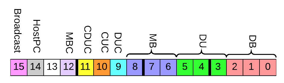
Fig. 54 Source/Destination address (16-bits)
Starting from least significant bit (LSB):
(2:0)   Detector Board Address
(5:3)   Detector Unit Address
(8:6)   Multiplexer Board Address
(9)     Detector Unit Controller source/destination flag
(10)    Coincidence Unit Controller source/destination flag
(11)    Coincidence Detector Unit Controller source/destination flag
(12)    Multiplexer Board Controller source/destination flag
(13)    Not used
(14)    Host PC source/destination flag
(15)    Broadcast flag
If the Broadcast flag is set in the destination address, the source node will pass the command down to all of its “children” and the child specified in the destination address will be read back to in order to create the response.
If the CUC or CDUC flags are set in the destination address, that corresponding unit will execute the command and respond. Namely, the response will not come from the unit specified in the destination address.
Finally, the payload is a 32-bit number that specifies additional information for each command; see below for examples.
Any operating system (Windows, GNU/Linux, or Mac OS) and programmable language (C, C++, Delphi, MATLAB, VB.NET, VC#, and Delphi) supported by QuickUSB can be used to interface with the OpenPET system. OpenPET provides multiple methods to control and configure the system. The simplest method is to use openpet.exe which is a Microsoft Windows executable that can configure and acquire data from an OpenPET system. Additionally, platform independent example Python scripts are also provided to streamline the configuration and acquisition process.
The executable openpet is used to control and configure the system. It has several optional arguments, list them by running openpet with -h or --help switches:
usage: openpet.py [-h] [-v] [-L] [-l] [-d DEVICEINDEX | -i INTERFACEINDEX]
    [-D IP]
    [-c ID DST PAYLOAD | -a DURATION | -sr FILE DST SIZE OFFSET | -sw FILE DST OFFSET]
    [-o FILE] [-t TIMEOUT] [-n RETRIES]

optional arguments:
  -h, --help            show this help message and exit
  -v, --verbose         Show debugging info.
  -L, --List            List network devices.
  -l, --list            List quickusb devices.
  -d DEVICEINDEX, --device DEVICEINDEX
                                                Quickusb device index.
                                                List devices to see indexes.
                                                DEFAULT=0
  -i INTERFACEINDEX, --interface INTERFACEINDEX
                                                Network interface device index.
                                                List devices to see indexes.
  -D IP, --destination IP
                                                IPv4 address of of destination node.
  -c ID DST PAYLOAD, --command ID DST PAYLOAD
                                                Sends a command to a destination
                                                module with a specific payload.
  -a DURATION, --acquire DURATION
                                                Acquire data for the specified
                                                duration (in seconds). Partial
                                                seconds are OK.
  -sr FILE DST SIZE OFFSET, --sram-read FILE DST SIZE OFFSET
                                                Reads SRAM contents from OpenPET and
                                                writes it to FILE.
  -sw FILE DST OFFSET, --sram-write FILE DST OFFSET
                                                Writes FILE contents to SRAM.
  -o FILE, --outputfile FILE
                                                File name to save acquired data.
  -t TIMEOUT, --timeout TIMEOUT
                                                Timeout duration (in seconds) between
                                                retries. Partial seconds are OK.
                                                DEFAULT=0.200
  -n RETRIES, --retries RETRIES
                                                Number of times I should try to
                                                contact OpenPET System before
                                                giving up. DEFAULT=20
Tables 8.1 and 8.2 show a list of the current OpenPET commands, including their command ID and a brief description of their function. The payload is specified for each command in the examples that follow.
| IDs | Name | Function |
|---|---|---|
| 0x0001 | Ping | Sends a single ping request to destination.
|
| 0x0002 | Write Children Bitstream | Command Support Board(s) to configure
all children boards from bitstream
stored in EPCS.
|
| 0x0003 | Write System Acquisition Mode | Sets the system mode register in
firmware to idle, scope, singles, etc.
|
| 0x0004 | Read System Acquisition Mode | Gets the system mode register
from firmware.
|
| 0x0005 | Write System Acquisition Mode Settings | Sets the system mode settings
register in firmware for the
mode selected.
|
| 0x0006 | Read System Acquisition Mode Settings | Gets the system mode settings
register from firmware.
|
| 0x0007 | Write System Acquisition Mode Action | Sets the system mode action register in
firmware to reset, start, stop.
|
| 0x0008 | Read System Acquisition Mode Action | Gets the system mode action register
from firmware.
|
| 0x0009 | Write Trigger Mask | Sets a mask to suppress triggers.
|
| 0x000A | Read Trigger Mask | Gets the mask from firmware.
|
| 0x000B | Write SRAM Data | Writes to external SRAM device.
Auto-increments address.
|
| 0x000C | Read SRAM Data | Reads from external SRAM device.
Auto-increments address.
|
| 0x000D | Zero out SRAM | SRAM content is zeroed out.
|
| 0x000F | Reset | Reset all configurations.
|
| 0x0010 | Read Node Type | Gets Node Type: CDUC, CUC, DUC, DB, etc.
|
| 0x0011 | Read Firmware and Software Version | Get firmware and software version.
|
| 0x0101 | Write TDC Configuration | Sets the TDC control register.
|
| 0x0102 | Read TDC Configuration | Gets the TDC control register.
|
| 0x0103 | Reset ADC Configuration | Command Detector Boards(s) to set ADCs
registers to OpenPET default values.
|
| 0x0104 | Write ADC Register | Writes a register directly on ADC(s).
See ADC datasheet for
valid register maps.
|
| 0x0105 | Reset DAC Configuration | Command Detector Board(s) to set DACs
registers to OpenPET default values.
|
| 0x0106 | Write DAC Register | Write a register directly on DAC(s).
See DAC datasheet for
valid register maps.
|
| 0x0107 | Write Sawtooth pulse(s) | Command DAC(s) to send sawtooth
pulses for a given duration of time.
|
| 0x0108 | Write Firmware Threshold | Sets a firmware threshold level
to trigger on.
|
| 0x0109 | Read Firmware Threshold | Gets the firmware trigger threshold.
|
| IDs | Name | Function |
|---|---|---|
| 0x0000 | (Reserved) Busy | Child doesn’t have anything to reply yet.
|
| 0xFFFF | (Reserved) Dead | Dead, nonexistent, or not programmed.
|
| 0x7F00 | SW Command is Unknown | Software (Running on NIOS) command id
is unknown to node.
|
| 0x7F01 | SW Command Timed Out | Software (Running on NIOS) command id
has timed out.
|
| 0x7F02 | Targeted Child is Dead | Targeted child is dead, nonexistent,
or not programmed.
|
| 0x7F03 | Targeted Child is Busy | Targeted child is busy processing
previous command.
|
| 0x7F04 | FW Command is Unknown | Firmware (Running on FPGA fabric)
command id is unknown to node.
|
| 0x7F05 | FW Command Timed Out | Firmware (Running on FPGA fabric)
command id has timed out.
|
| 0x7F06 | SW incomplete packet | Software (Running on NIOS) received
incomplete OpenPET command
|
| 0x7F07 | SW interrupt
routine can’t keep up
|
Software (Running on NIOS) received packets
faster than it can handle.
|
Description and Examples of Command IDs
Command ID: 0x0001
Description: Sends a single ping request to destination. If broadcast on DST was specified, then the read back will be performed on the address provided.
Payload: None e.g. 0 or any value.
Examples:
Send a ping command using the openpet executable to destination 0x0002 i.e., DB in slot 2 with 0 payload. openpet will print out the date, time, message type, [S]ENT or [R]ECEIVED indicator, command id, destination (when sending) or source (when receiving) address, and the payload. Note that the MSB of the command ID is set to ‘1’ when receiving.:
$ openpet -c 0x0001 0x0002 0

2015-09-01 12:30:00,529 INFO [S] 0x0001 0x0002 0x00000000
2015-09-01 12:30:00,733 INFO [R] 0x8001 0x0002 0x00000000
Just like the first example, however, using decimal numbers instead of hex:
$ openpet -c 1 2 0
The destination address has the broadcast flag set to 1. This will cause the SB to send the ping command to all its children, however, the reply will be read back only from 0x0002:
$ openpet -c 0x0001 0x8002 0
The asynchronous flag in the command id is set to 1. This will cause the SB to immediately respond to the HostPC regardless if the ping command was successful on 0x0002 or not. This feature becomes useful when sending commands that take minutes to complete. Note, that the targeted destination will not be able to respond until it completes the execution of the asynchronous command, however, other nodes can be accessed and controlled independently:
$ openpet -c 0x1001 0x0002 0
QuickUSB device index 1 is used instead of the default device:
$ openpet -d 1 -c 1 2 0
Using Ethernet instead of default QuickUSB device. By default the IP address of the OpenPET chassis is 10.10.10.2:
$ openpet -D 10.10.10.2 -c 1 2 0
The HostPC is willing to wait 1 second for the SB to provide a valid reply. The default timeout per try is 200ms:
$ openpet -t 1 -c 1 2 0
The HostPC tries a maximum of 3 times before giving up on the SB. The wait between each trial is 0.5 second:
$ openpet -n 3 -t 0.5 -c 1 2 0
More debugging information is displayed:
$ openpet -v -c 1 2 0
Command ID: 0x0002
Description: FPGA bitstream configuration is read from EPCS flash memory then written to all children. This command is executed on power-up by default.
Payload: None e.g. 0 or any value.
Examples:
Ask CDUC to configure all of its children i.e., detectorboard FPGAs (not io):
$ openpet -c 2 0x0800 0
Command ID: 0x0003
Description: Writes the System Acquisition Mode register in firmware.
Payload:

Fig. 55 System Acquisition Mode payload
Starting from least significant bit (LSB)
(3:0)  Mode
(31:4) not used
Available Modes:
IDLE 0x0 Oscilloscope 0x1 Singles 0x2
Note
When setting the System Acquisition Mode it is important to set the command broadcast bit to 1. Advanced users have the flexibility of toggling the broadcast bit based on their application.
Examples:
Broadcast to all nodes to set System Acquisition Mode to scope mode. The command acknowledgment is received from DB in slot 3:
$ openpet -c 3 0x8003 1
Command ID: 0x0004
Description: Reads the System Acquisition Mode register from firmware.
Payload: None e.g. 0 or any value.
Examples:
Read the System Acquisition Mode register from firmware from slot 5. The payload of the reply is the mode that was previously set i.e., 1=scope mode:
$ openpet -c 4 5 0xDEADFEED

2015-09-02 11:10:00,528 INFO [S] 0x0004 0x0005 0xDEADFEED
2015-09-02 11:10:00,732 INFO [R] 0x8004 0x0005 0x00000001
Command ID: 0x0005
Description: Writes the System Acquisition Mode Settings register in firmware. The 32-bit setting payload value depends on the mode set in Command ID 0x0003.
Payload:
- Payload when System Acquisition Mode = 0x1 = Oscilloscope (scope mode):

Fig. 56 System Acquisition Mode Settings payload for oscilloscope mode
Starting from least significant bit (LSB)
(3:0)   Reserved: Must be 0001
(12:4)  Total Number of ADC samples, see notes below (zero is accounted for)
(15:13) Reserved
(19:16) Number of ADC samples before energy trigger (2^4 = 16)
(23:20) Reserved
(27:24) Trigger window (2^4 = 16)
(31:28) Reserved
- Payload when System Acquisition Mode = 0x2 = Singles (singles mode):

Fig. 57 System Acquisition Mode Settings payload for singles mode
Starting from least significant bit (LSB)
(3:0) Number of samples to integrate, i.e., Integration length
(7:4) Reserved
(15:8) Reserved
(19:16) Integration starting point
(31:24) Not Used
Note
- Scope Mode:
- Total Number of samples should be greater than samples before trigger + trigger window.
- Total Number of samples should not exceed Firmware’s maximum number of samples - (Number of Channel headers + Detector Board Header)
- Singles Mode:
- A and B are defined visually in Fig. 44
- Integration Length should be greater than 1.
- Number of pipeline stages is pre-defined in the firmware as a constant
- PipelineStages = ceil(EventCompuationClockTicks/SliceWidth) + 1 , where ceil() rounds the number to the next highest integer.
- The trigger location is always set at time bin = 16 in the firmware. In other words, the number of samples before the energy trigger are always 16.
- Baseline is computed as the average of samples located between [0 to 16-B].
Examples:
Broadcast to all nodes to set System Acquisition Mode to scope mode. Then use data format = 1, 16 samples, 0 samples before trigger, and a trigger window to 2:
$ openpet -c 3 0x8003 1
$ openpet -c 5 0x8003 0x02000101
Broadcast to all nodes to set System Acquisition Mode to singles mode. Then TODO FIXME:
$ openpet -c 3 0x8003 2
$ openpet -c 5 0x8003 0x00000001
Note
If the user sets a parameter with a value that is too large, the system will set the parameter to the maximum possible value. This will be evident in the response payload. It will show the maximum possible value instead of the user’s value. The user can then decide to continue or change it.
Command ID: 0x0006
Description: Reads the System Acquisition Mode Settings register from firmware.
Payload: None e.g. 0 or any value.
Examples:
Reads the System Acquisition Mode Settings register from firmware from slot 3. The payload of the reply is set to the settings previously specified, e.g., scope mode settings:
$ openpet -c 6 3 0xDEADFEED

2015-09-02 11:10:00,528 INFO [S] 0x0006 0x0003 0xDEADFEED
2015-09-02 11:10:00,732 INFO [R] 0x8006 0x0003 0x02000101
Command ID: 0x0007
Description: Writes the System Acquisition Mode Action register in firmware.
Payload:

Fig. 58 System Acquisition Mode Action payload
Starting from the least significant bit (LSB)
(3:0)  Action
(31:4) not used
Available actions:
Reset 0x0 Stop 0x1 Run 0x2
Note
When setting the System Acquisition Settings it is important to set the command broadcast bit to 1. Advanced users have the flexibility of toggling the broadcast bit based on their application.
Examples:
Reset the System Acquisition Mode and Settings (payload = 0x0):
$ openpet -c 7 0x8003 0x00000000
Stop the current system acquisition (payload = 0x1):
$ openpet -c 7 0x8003 0x00000001
First, broadcast to all nodes to set System Acquisition Mode to scope mode. Then use data format = 0, 16 samples, 0 samples before trigger, and a trigger window to 2. Finally, run the acquire data command (payload = 0x2):
$ openpet -c 3 0x8003 1
$ openpet -c 5 0x8003 0x02000100
$ openpet -c 7 0x8003 0x00000002
Command ID: 0x0008
Description: Reads the System Acquisition Mode Action register from firmware.
Payload: None e.g. 0 or any value.
Examples:
Reads the System Acquisition Mode Action register from firmware from slot 3. The payload of the reply is set to the action previously specified, e.g., reset = 0:
$ openpet -c 8 3 0xDEADFEED

2015-09-02 11:10:00,528 INFO [S] 0x0008 0x0003 0xDEADFEED
2015-09-02 11:10:00,732 INFO [R] 0x8008 0x0003 0x00000000
If action previously set to terminate the current action, e.g., stop = 1:
$ openpet -c 8 3 0xDEADFEED

2015-09-02 11:10:00,528 INFO [S] 0x0008 0x0003 0xDEADFEED
2015-09-02 11:10:00,732 INFO [R] 0x8008 0x0003 0x00000001
If action previously set to run the system acquisition, e.g., run = 2:
$ openpet -c 8 3 0xDEADFEED

2015-09-02 11:10:00,528 INFO [S] 0x0008 0x0003 0xDEADFEED
2015-09-02 11:10:00,732 INFO [R] 0x8008 0x0003 0x00000002
Command ID: 0x0009
Description: Writes a mask to suppress triggers in firmware.
Payload:

Fig. 59 Trigger mask payload
Starting from the least significant bit (LSB)
(31:0) 1 bit per channel.  Set bit to 1 to enable trigger on that channel.
Example:
Set trigger masks for channels 0, 5, and 8 in detector board 5:
$ openpet -c 9 5 0x00000121
Command ID: 0x000A
Description: Reads the trigger mask from firmware.
Payload: None e.g. 0 or any value.
Example:
Reads the trigger mask previously set in detector board 5:
$ openpet -c 10 5 0xDEADFEED

2015-09-02 11:10:00,528 INFO [S] 0x000A 0x0005 0xDEADFEED
2015-09-02 11:10:00,732 INFO [R] 0x800A 0x0005 0x00000121
Command ID: 0x000B
Description: Writes to external SRAM device. Auto-increments address.
Payload:
Starting from the least significant bit (LSB)
(31:0) Value to write to SRAM
Caveats: The Mode Action has to be in Reset for this command to work correctly.
Example:
Write some value to external SRAM in detector board 1 at location 4 (Note that command 0x000C is used to set the address of the starting location):
$ openpet -c 12 1 4
$ openpet -c 11 1 0x12345678

2015-10-12 11:02:33,115 INFO [S] 0x000B 0x0001 0x12345678
2015-10-12 11:02:33,355 INFO [R] 0x800B 0x0001 0x12345678
- Alternative: -sw option
Write to SRAM in detector board 1 from file sramtest.bin starting from the top (offset = 0):
$ openpet -sw sramtest.bin 1 0

2015-10-12 11:05:22,956 INFO Writing content to SRAM.
2015-10-12 11:05:28,385 INFO Done SRAM writing.
Command ID: 0x000C
Description: Reads from external SRAM device. Auto-increments address.
Payload:
Starting from the least significant bit (LSB)
(31:0) SRAM address
Caveats: The Mode Action has to be in Reset for this command to work correctly.
Example:
Read data starting from SRAM address 0 in detector board 1:
$ openpet -c 12 1 0

2015-10-12 11:02:41,956 INFO [S] 0x000C 0x0001 0x00000000
2015-10-12 11:02:42,165 INFO [R] 0x800C 0x0001 0x12345678
- Alternative: -sr option
Read 100 values from SRAM to file sramtest.bin from detector board 1 starting from the top (offset = 0):
$ openpet -sr sramtest.bin 1 100 0

2015-10-12 11:03:11,296 INFO Reading SRAM content.
2015-10-12 11:03:15,635 INFO Done Reading SRAM Content.
Command ID: 0x000D
Description: Clears SRAM content. Sets to zero.
Payload: None e.g. 0 or any value.
Example:
Clears SRAM content on detector board 1:
$ openpet -c 13 1 0xDEADFEED

2015-10-09 11:10:00,528 INFO [S] 0x000D 0x0001 0xDEADFEED
2015-10-09 11:10:00,732 INFO [R] 0x800D 0x0001 0x00000000
Command ID: 0x000F
Description: System wide reset. It resets the configurations of firmware, software, and peripheral hardware to default values.
Payload: None e.g. 0 or any value.
Example:
Broadcast a reset to all nodes and get a reply from 0x1:
$ openpet -c 0xF 0x8001 0

2015-10-09 11:10:00,511 INFO [S] 0x000F 0x8001 0x00000000
2015-10-09 11:10:00,733 INFO [R] 0x800F 0x8001 0x00000000
Command ID: 0x0010
Description: Get Node Type for target.
Payload: None e.g. 0 or any value.
Available Note Types:
CUC 0x0 MB 0x1 DUC 0x2 DB 0x3 CDUC 0x4
Note
Brute force all controller addresses to discover the top most parent node.
Example:
Read node type from a controller. Note you might need to brute force all nodes to discover the tree. Reply here is 0x00000004 which means that the node is a CDUC:
$ openpet -c 0x0010 0x0800 0

2016-08-01 18:22:26,203 INFO [S] 0x0010 0x0800 0x00000000
2016-08-01 18:22:26,405 INFO [R] 0x8010 0x0800 0x00000004
Command ID: 0x0011
Description: Get OpenPET firmware and software version.
Payload: None e.g. 0 or any value.
Format: Format is 0xMMNNS where MM means major, NN, means minor, and S is subminor. Major and minor versions are 8-bits. Subminor is 4-bits.
Example:
Read version from a CDUC controller. Reply is 0x00002031 which means major is 2, minor is 3, and subminor is 1. That is version 2.3.1:
$ openpet -c 0x0010 0x0800 0

2016-08-01 18:26:35,055 INFO [S] 0x0011 0x0800 0x00000000
2016-08-01 18:26:35,256 INFO [R] 0x8011 0x0800 0x00002031
Command ID: 0x0101
Description: Sets the TDC control register.
Payload:

Fig. 60 Payload for TDC control register
Starting from the least significant bit (LSB)
(7:0)   TDC command
(31:8)  Not used
Available TDC commands:
Reset 0x80 Calibrate 0x02 Run 0x04
Examples:
Set the TDC control register to reset in detector board 5:
$ openpet -c 0x0101 5 0x00000080
Set the TDC control register to calibrate in detector board 5:
$ openpet -c 0x0101 5 2
Set the TDC control register to run in detector board 5:
$ openpet -c 0x0101 5 4
Command ID: 0x0102
Description: Gets the TDC control register.
Payload: None e.g. 0 or any value.
Example:
Reads the current TDC control register from detector board 5, e.g., run = 1:
$ openpet -c 0x0102 5 0xDEADFEED

2015-10-09 11:10:00,528 INFO [S] 0x0102 0x0005 0xDEADFEED
2015-10-09 11:10:00,732 INFO [R] 0x8102 0x0005 0x00000001
Command ID: 0x0103
Description: Resets ADC configuration. Commands Detector Board(s) to set ADC registers to OpenPET default values.
Payload: None e.g. 0 or any value.
Example:
Resets ADC registers on detector board 3 to default OpenPET values:
$ openpet -c 0x0103 3 0xDEADFEED

2015-10-09 11:10:00,528 INFO [S] 0x0103 0x0003 0xDEADFEED
2015-10-09 11:10:00,732 INFO [R] 0x8103 0x0003 0x00000000
Command ID: 0x0104
Description: Writes ADC register. See ADS5282 datasheet for valid register maps.
Payload:

Fig. 61 Payload to write ADC register
Starting from the least significant bit (LSB)
(15:0)   ADC data (see ADS5282 datasheet, page 17)
(17:16)  Reserved
(25:18)  ADC register address (see ADS5282 datasheet, page 17)
(26)     Reserved
(27)     ADC chip address (0 for channel 0-7; 1 for channel 8-15)
(29:28)  Reserved
(30)     Not used
(31)     Broadcast flag, i.e., run on all ADC chips
Note
The ADC address and ADC data for the corresponding DB channel when setting the ADC gain. Each gain is set using 4 bits ranging from 0-12 dB. The gain has to be set on four channels at a time (i.e., 16-bit ADC data).
| ADC Chip Address | ADC Address | ADC Data (MSB to LSB) |
|---|---|---|
| 0x0 | 0x2A | Channel 3 to 0 |
| 0x0 | 0x2B | Channel 4 to 7 |
| 0x1 | 0x2A | Channel 11 to 8 |
| 0x1 | 0x2B | Channel 12 to 15 |
Examples:
Sets the ADC gain to 6 dB for channels 4 to 7 on the Detector Board in slot 3 without broadcasting:
$ openpet -c 0x0104 0x0003 0x00AC6666
- Payload breakdown (LSB to MSB):
- 0x00AC6666 (=0 0 00 0 0 00101011 00 0110011001100110)
- Bits 15-0: 0110011001100110 (see ADS5282 datasheet, page 17)
- Bits 17-16: Reserved
- Bits 25-18: 0x2B indicates for channel 4 to 7
- Bits 26: Reserved
- Bits 27: 0 indicates for channel 4 to 7
- Bits 29-28: Reserved
- Bits 30: Not used
- Bits 31: 0 indicates not a broadcast command
Sets the ADC gain to 8 dB for channels 8 to 11 on the Detector Board in slot 5 with broadcasting:
$ openpet -c 0x0104 0x0005 0x88A88888
- Payload breakdown (LSB to MSB):
- 0x88A88888 (=1 0 00 1 0 00101010 00 1000100010001000)
- Bits 15-0: 1000100010001000 (see ADS5282 datasheet, page 17)
- Bits 17-16: Reserved
- Bits 25-18: 0x2A indicates for channel 8 to 11
- Bits 26: Reserved
- Bits 27: 1 indicates for channel 8 to 11
- Bits 29-28: Reserved
- Bits 30: Not used
- Bits 31: 1 indicates broadcast command
Command ID: 0x0105
Description: Resets DAC configuration. Commands Detector Board(s) to set DAC registers to OpenPET default values.
Payload: None e.g. 0 or any value.
Example:
Resets DAC registers on detector board 3 to default OpenPET values:
$ openpet -c 0x0105 3 0xDEADFEED

2015-10-09 11:10:00,528 INFO [S] 0x0105 0x0003 0xDEADFEED
2015-10-09 11:10:00,732 INFO [R] 0x8105 0x0003 0x00000000
Command ID: 0x0106
Description: Writes DAC register. See DAC LTC2634 datasheet for valid register maps.
Payload:

Fig. 62 Payload to write DAC register
Starting from the least significant bit (LSB)
(9:0)   DAC data (see LTC2634 datasheet, page 20)
(12:10) Reserved
(16:13) DAC address (see LTC2634 datasheet, page 20)
(20:17) DAC command (see LTC2634 datasheet, page 20)
(22:21) Reserved
(26:23) DAC chip address
(28:27) DAC type (00=energy, 01=timing, 10=reserved, 11=all)
(30:29) Not used
(31)    Broadcast flag, i.e., run on all DAC chips for a given type
Note
DAC Command=0x3 to set DAC voltage (10-bit data)
| Type | Bits 28-27 | DAC Full Scale |
|---|---|---|
| Energy | 00 | 4.096 V |
| Timing | 01 | 2.500 V |
| Reserved | 10 | 2.500 V |
The DAC address and DAC chip select for the corresponding DB channel when setting the energy and timing DAC. Because a chip has four DAC, a single DAC voltage can be set to four channels with one command.
| Channel | DAC Address | DAC Chip Address |
|---|---|---|
| 0 | 0x0 | 0x0 |
| 1 | 0x1 | 0x0 |
| 2 | 0x2 | 0x0 |
| 3 | 0x3 | 0x0 |
| 4 | 0x0 | 0x1 |
| 5 | 0x1 | 0x1 |
| 6 | 0x2 | 0x1 |
| 7 | 0x3 | 0x1 |
| 8 | 0x0 | 0x2 |
| 9 | 0x1 | 0x2 |
| 10 | 0x2 | 0x2 |
| 11 | 0x3 | 0x2 |
| 12 | 0x0 | 0x3 |
| 13 | 0x1 | 0x3 |
| 14 | 0x2 | 0x3 |
| 15 | 0x3 | 0x3 |
| 0-3 | 0xF | 0x0 |
| 4-7 | 0xF | 0x1 |
| 8-11 | 0xF | 0x2 |
| 12-15 | 0xF | 0x3 |
- The timing DAC is usually set to a low threshold to obtain the best timing.
- The energy DAC determines whether readout is initiated, and so is usually set to a higher threshold to reduce noise triggers (see 16-Channel Detector Board).
Examples:
Sets DAC energy threshold to +1.150V for channel 4 on the Detector Board in slot 3 without broadcasting:
$ openpet -c 0x0106 0x0003 0x00860120
- Payload breakdown (LSB to MSB):
- 0x000860120 (=0 00 00 0001 00 0011 0000 000 0100100000)
- Bits 9-0: 0100100000 (1024*1.15/4.096)
- Bits 12-10: Reserved
- Bits 16-13: 0x0 (channel 4 in chip select 0x1)
- Bits 20-17: 0x3 (see DAC LTC2634 datasheet, page 20)
- Bits 22-21: Reserved
- Bits 26-23: 0x1 indicates this is the chip where channel 4 resides
- Bits 28-27: 00 indicates that the DAC type is energy
- Bits 30-29: Not used
- Bits 31: 0 indicates not a broadcast command
Sets DAC timing threshold to +0.5V for channel 12 on the Detector Board in slot 5 with broadcasting:
$ openpet -c 0x0106 0x0005 0x898600CD
- Payload breakdown (LSB to MSB):
- 0x898600CD (=1 00 01 0011 00 0011 0000 000 0011001101)
- Bits 9-0: 0011001101 (1024*0.5/2.5)
- Bits 12-10: Reserved
- Bits 16-13: 0x0 (channel 12 in chip select 0x3)
- Bits 20-17: 0x3 (see DAC LTC2634 datasheet, page 20)
- Bits 22-21: Reserved
- Bits 26-23: 0x3 indicates this is the chip where channel 12 resides
- Bits 28-27: 01 indicates that the DAC type is timing
- Bits 30-29: Not used
- Bits 31: 1 indicates a broadcast command
Command ID: 0x0107
Description: Writes Sawtooth pulse(s). Commands DAC(s) to send sawtooth pulse(s) for a given duration of time.
Payload:

Fig. 63 Payload to write sawtooth pulse
Starting from the least significant bit (LSB)
(3:0)   DAC chip address
(5:4)   DAC type
(13:6)  Number of sawtooth pulses to send
(30:14) Not used
(31)    Broadcast flag, i.e., run on all DAC chips for a given type
Note
The time it takes to execute and finish this command depends on the number of sawtooth pulses you request. It is highly advised to send this command as an asynchronous command (non-blocking) by setting the MSB on CMD ID to ‘1’.
Example:
Command DAC to send 100 sawtooth pulses to detector board 3. DAC type is 00 which is energy, and chip address is 0x2. Broadcast flag is set to 1, and the CMD ID MSB is set to 1 for asynchronous command:
$ openpet -c 0x8107 0x0003 0x80001902
Command ID: 0x0108
Description: Sets a firmware threshold level to trigger on.
Payload:

Fig. 64 Payload to set firmware trigger threshold
Starting from the least significant bit (LSB)
(11:0)   Threshold value
(15:12)  Reserved
(17:16)  Mode (00=off, 01=on)
(31:18)  Not used
Note
The minimum and maximum threshold values correspond to the minimum and maximum of the ADC signal which is 2Vpp. The 0V value is in the middle so to set at the 0V DC, set the MSB of the threshold value to 1. To set the maximum threshold value (1V), flip all bits 0 to 11 to 1. To set the minimum threshold value (-1V), flip all bits 0 to 11 to 0.
Example:
Sets the firmware threshold level to 0V and mode ‘on’ for detector board 5:
$ openpet -c 0x0108 0x0005 0x00010800
Command ID: 0x0109
Description: Gets the firmware trigger threshold.
Payload: None e.g. 0 or any value.
Example:
Retrieves the firmware trigger threshold previously set on detector board 5:
$ openpet -c 0x0109 0x0005 0xDEADFEED

2015-10-09 11:10:00,528 INFO [S] 0x0109 0x0005 0xDEADFEED
2015-10-09 11:10:00,732 INFO [R] 0x8109 0x0005 0x00010800