Appendices
Appendix 1: Default Values
Firmware Defaults (found in fw directory)
- Acquisition mode = 0x0 = idle
- Acquisition mode settings = 0x0
- Acquisition mode action = 0x0 = reset
- Trigger Mask = 0xFFFFFFFF = all channels enabled
- Debug ports are disabled
- SupportBoard Node Type = CDUC
- Main CLK Frequency = 80 MHz (Not programmable)
- Slice CLK Frequency = Main CLK Freq / 8 = 80/8 = 10 MHz = 100 ns
- QuickUSB Bus Width = 16 bits
- Number of QuickUSB packets (write cycles) to complete a single OpenPET command = 5
- QuickUSB output FIFO depth = 16 * 256. Should be more than 128. The larger the better.
- Total Number of Scope mode samples (DB fifo depth) = 128
- Number of Channels per ADC chip = 8
- Number of ADC chips = 2
- ADC resolution = 12
- TDC resolution = 19
- TDC core (Multiphase) is enabled
- Scope mode core is enabled
- Singles mode example core is enabled (computes energy for first four channels)
- Firmware threshold for scope mode is disabled by. Default threshold is set to FFFF.
- Firmware based trigger is not available in Singles mode.
Software Defaults (found in hostpc directory)
QuickUSB Data bus width = 16 # QuickUSB Data bus width
Number of QuickUSB packets (write cycles) to complete a single OpenPET command = 5
Source Address = 0x4000
QuickUSB Settings default values except for the following registers:
- Register 1 = 0x0001, bus width = 16-bits
- Register 2 = 0xC000, address bus is disabled not and incremented
- Register 3 = 0x0002, IFLCK is disabled, polarity is normal, GPIF master mode
- Register 5 = 0x8010, Allow high speed, CPU running at 48MHz, CLKOUT is disabled
QuickUSB streaming call back timeout = 50 ms
QuickUSB streaming buffers = 8
QuickUSB streaming buffer size = 1 MB (this is the max)
Default data output file name is strftime(“%Y%m%d-%H%M%S”) + “.openpetd”
Data output file compression is disabled
Number of command retires = 20
Timeout between retries = 200 ms
Acquisition time = 10 seconds
Scope trigger window = 5
Scope samples before trigger = 6
Scope number of samples = 32
Scope format = 0
DAC thredhold = 200 mv
Process data before writing to file = true
Acquisition mode = 0 = idle
Acquisition mode settings = 0 = none
Embedded Software Defaults (found in sw directory)
- SupportBoard JTAG UART has enable_jtag_uart_ignore_fifo_full_error = true
- DetectorBoard JTAG UART is disabled
- Number of CLK ticks in order to complete a single software-firmware command = 4096
- SupportBoard SPI interface command timeout = 200 ms
- SupportBoard SPI interface retries before giving up on slave = 8
NIOS Peripheral Hardware Defaults (found in sw directory)
- ADC defaults are equal to datasheet defaults (i.e., gain=0 dB) except register 0x42 is set to 0x8005, i.e., a differential input clock is used on the ADC instead of singled ended.
- Timing DAC defaults are equal datasheet defaults except DAC level is set to 122.1 mV
- Energy DAC defaults are equal datasheet defaults except DAC level is set to 200 mV
- Ramp DAC defaults are equal datasheet defaults except DAC level is set to 0 mV
Appendix 2: Troubleshooting Diagnostics
Using the command sequence listed in Example System Setup & Data Acquisition of a Small System in Oscilloscope Mode is a simple way to test if your OpenPET system has been properly set up to take data. However, if you are not properly acquiring data, further diagnosis will be necessary. This appendix outlines three basic tests for troubleshooting your OpenPET system. Data analysis can be performed with the provided HostPC Python Software, which is available on the OpenPET website. You can also develop your own analysis software or use the OpenPET Control and Analysis optional software tool (see OpenPET Control and Analysis Tools (OpenPET CAT)).
Test With Internal Trigger
The first step in troubleshooting is to discern if the basic support board and detector board digital command and data communication chain is functioning properly. This test does not require a signal input since the detector board generates the counter data input internally.
First, you need to set up the OpenPET hardware and install the firmware and software by following the instructions detailed in Getting Started. After that, POWER CYCLE your chassis. You can then configure the system and acquire test communication data. An example command sequence for a single detector board in slot 3 is shown below.
Step 1 - Ping the detector board in slot 3:
$ openpet -c 1 3 0

2015-09-01 12:30:00,529 INFO [S] 0x0001 0x0003 0x00000000
2015-09-01 12:30:00,733 INFO [R] 0x8001 0x0003 0x00000000
If you get an error at this step, check the following:
- Are the detector board and support board programmed correctly?
- Did you reboot your chassis?
- Are the detector board slots correct? Remember, slots are numbered 0 to 7.
If the error persists after these things have been checked, the detector board may be physically damaged.
Step 2 - Check firmware version and node type. To figure out the node type:
$ openpet -c 0x0010 0x0800 0

2016-08-01 18:22:26,203 INFO [S] 0x0010 0x0800 0x00000000
2016-08-01 18:22:26,405 INFO [R] 0x8010 0x0800 0x00000004
0x00000004 means that the node is a CDUC. Note you might need to brute force all possible nodes to discover the tree. e.g. try addresses 0x0400 and 0x0200 for CUC and DUC. Next, check which firmware is flashed on the board:
$ openpet -c 0x0010 0x0800 0

2016-08-01 18:26:35,055 INFO [S] 0x0011 0x0800 0x00000000
2016-08-01 18:26:35,256 INFO [R] 0x8011 0x0800 0x00002031
The command above reads the firmware version from the CDUC controller. Reply is 0x00002031 which means major is 2, minor is 3, and subminor is 1. That is version 2.3.1.
Step 3 - Configure ADC to send out fixed pattern output “PAT SYNC”:
$ openpet -c 0x0104 3 0x81140002
Step 4 - Change mode to Scope and configure its settings to 16 samples, 0 samples before trigger, and a trigger window of 2:
$ openpet -c 3 0x8003 1
$ openpet -c 5 0x8003 0x02000100
Step 5 - Bypass hardware trigger circuitry and use internal firmware trigger logic using a very small threshold:
$ openpet -c 0x108 0x8003 0x00010001
Step 6 - Acquire data for 5 seconds:
$ openpet -a 5

2015-10-23 11:41:34,368 INFO Starting qusb data acquisition...
2015-10-23 11:41:39,861 INFO 0.127s remaining.
2015-10-23 11:41:40,000 INFO QUSB rate is 41.048 MB/s
2015-10-23 11:41:40,000 INFO Stopping qusb data stream...
2015-10-23 11:41:40,000 INFO QUSB data stream has stopped.
2015-10-23 11:41:40,000 INFO Stopping qusb data queue [0]...
2015-10-23 11:41:40,000 INFO QUSB data queue has stopped.
A unique file name 20151023-114134.openpetd is created. The file size should be around 200 MB. Now use the plot.py script to view the data:
$ python plot.py 20151023-114134.openpetd
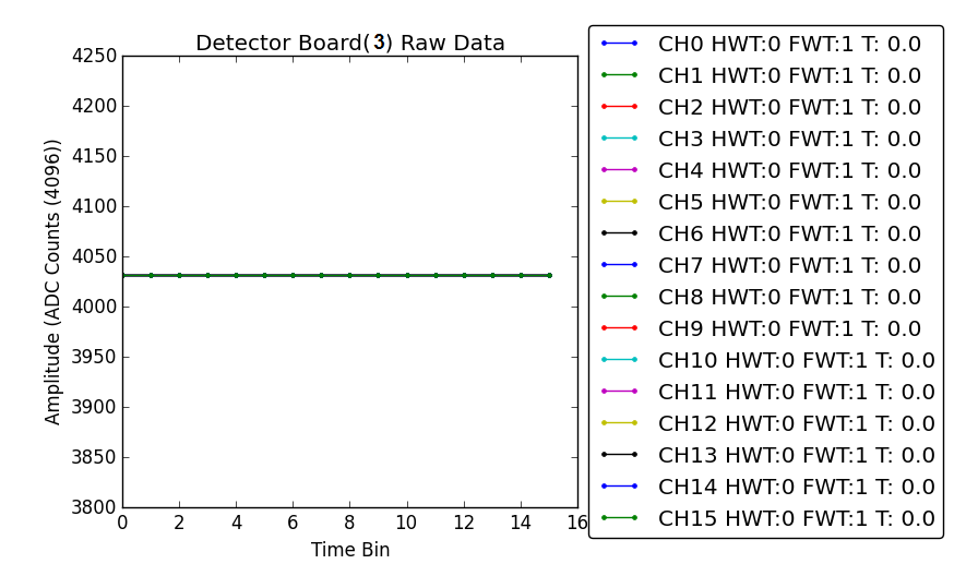
Fig. 88 ADC PAT SYNC pattern plot
Test With External Trigger
For this next test, you need to set up the OpenPET hardware and install the firmware and software by following the instructions detailed in Getting Started. After that, POWER CYCLE your chassis. You can then configure the system and acquire test communication data using the Simple Example for a single detector board in slot 3.
Test Trigger
If you have confirmed that your digital communication chain and analog circuitry are functioning properly with the two tests described above, then you need to check your detector signals and trigger. Specifically, you should check your trigger mask and DAC settings to make sure that your trigger thresholds are set properly for the input signals from your detector module (see Command ID: 0x0009 and Command ID: 0x000A for more details on how to set and read the trigger mask).