Getting Started
Getting Hardware
The OpenPET system uses a custom Support Crate that is similar to a VME crate (see Support Crate). Support Crates should be purchased through Elma: Support Crate Chassis, part number 12V12XXX78N2VCGX-LBL, http://openpet.lbl.gov/purchase/.
The OpenPET PC boards can be purchased from Terasic through their OpenPET website at http://www.openpet.terasic.com. For a small system in the first release, each Detector Unit (see Detector Unit) requires the following OpenPET boards:
- 1 Support Board
- 1-8 16-Channel Detector Boards
You also need the following additional components:
- 1 Host PC with a Windows 7 or Windows 10 operating system.
- 1 QuickUSB module: Bitwise Systems, part number QUSB2, http://www.bitwisesys.com/qusb2-p/qusb2.htm.
- 1 standard USB cable
- 1 USB-Blaster Cable: Terasic, Digi-Key part number P0302-ND, http://www.digikey.com/product-highlights/us/en/terasic-usb-blaster-cable/3718.
- Multiplexer Board/Coincidence Interface Board, http://www.openpet.terasic.com (only for Standard System)
The QuickUSB module is a small PC board that contains circuitry to provide high-speed USB 2.0 capability. It is plugged into either the Host PC Interface Board or the Support Board. The USB-Blaster cable interfaces between a USB port on the Host PC to the Altera main FPGA on the Support Board, so configuration data can be sent from the PC to the FPGAs. More detailed instructions are provided in the following sections.
Assembling the Hardware
Warning
All OpenPET parts are Electrostatic Sensitive Devices. Connect ground wire before touching any ESD.
Once you receive the parts for an OpenPET support crate, some minor assembly is required. Fig. 9 shows the two main components: the empty Support Crate and the Support Board. In addition, you will receive a small custom jumper board (see Fig. 10c). You will also need a standard power cable for the crate, M2.5 x 12 mm Phillips head screws, M4 x 5 mm Phillips head screws, and appropriate screw drivers.
The first assembly step is to attach the Support Board to the crate. From the back side of the crate, align the screw holes on the Support Board to those on the Support Crate and secure it using M2.5 x 12 mm Phillips head screws. We recommend using at least 3 screws on the top, middle and bottom rows. It is also useful to place a piece of paper across the fans during assembly so any dropped screws don’t fall into them. When the board is properly aligned, there should be about a 4 mm gap between the right edge of the Support Board and the right side of the Support Crate (Fig. 10a).
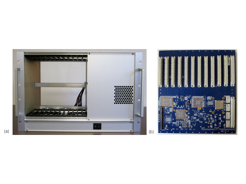
Fig. 9 (a) Empty Support Crate viewed from the front. (b) Support Board viewed from the front.
Once the Support Board is secured on the crate, you need to attach the power cables. The power cables and Support Board connectors are labeled. From bottom to top, the power cables are -5 V (orange cable), ground (black cables), +3.3 V (purple cables) and +5 V (red cable), as shown in Fig. 10b. Secure these power cables on to their respective Support Board connectors using M4 x 5 mm Phillips head screws. You may need to feed each screw through the power cable lug nut before attaching it to the Support Board, since the lug nuts fit tightly. In addition, there is a small bundle of cables that can be used for monitoring but these cables are not needed.
Finally you need to plug the custom small jumper board into the back of the Support Board. It plugs in to the connector just to the right of the Jtag connector (see Fig. 10c). Specifically, board plugs into the left column of pins on the connector (which is marked main, 58, 62, 65, 68). This jumper board identifies that the Jtag should communicate with the main FPGA on the Support Board.
The Support Board is shipped with the board receiving its system clock locally as set by a jumper J10 shorting pin 1 and 2 as shown in Fig. 11a, which is the setting for a Small System SB (i.e., DU in Fig. 4) and the master SB in a Standard System (i.e., CU in Fig. 5). The slave SB in a Standard System (i.e., DUs in Fig. 5) will need the jumper J10 shorting pin 2 and 3 as shown in Fig. 11b, which set the SB to receive its system clock from the CU instead of locally.
The fully assembled Support Crate is shown in Fig. 12.
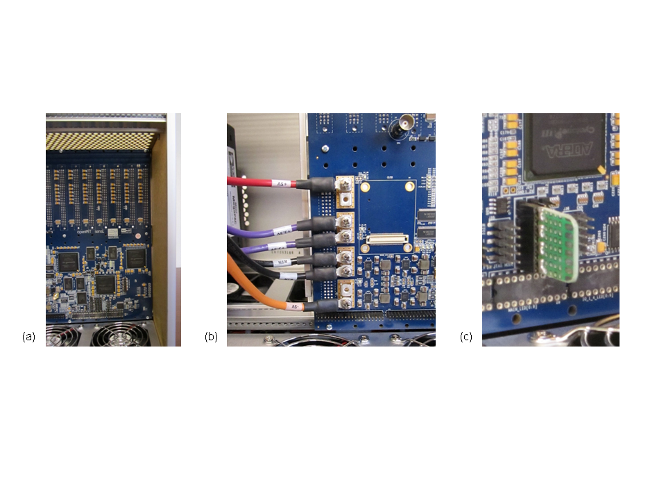
Fig. 10 (a) Close up of the small gap (~4 mm) between the Support Crate and the edge of the Support Board when assembled properly. (b) Close up of the power cables attached to the back of the Support Board. (c) Close up of the jumper board plugged into the back of the Support Board.
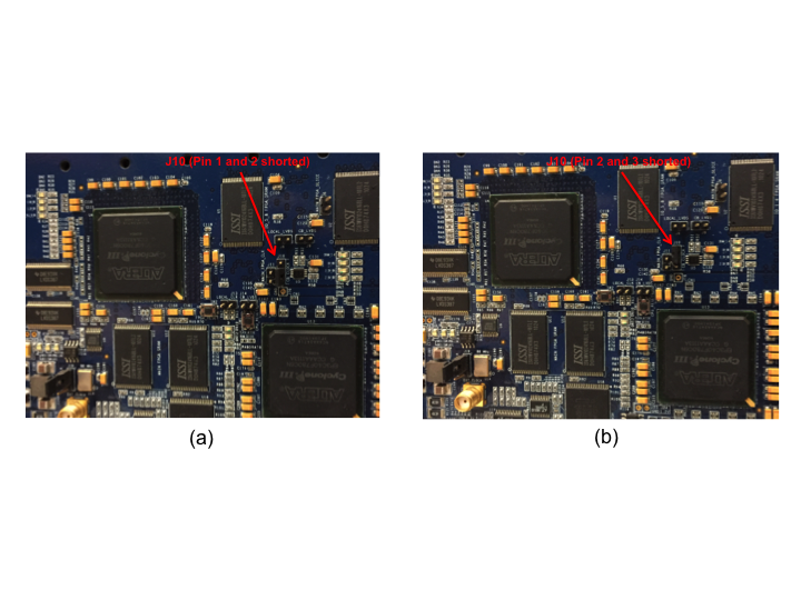
Fig. 11 (a) Jumper J10 on the SB shorting on pin 1 and 2 for a Small System and CU in a Standard System. (b) Jumper J10 on the SB shorting on pin 2 and 3 for the DUs in a Standard System.
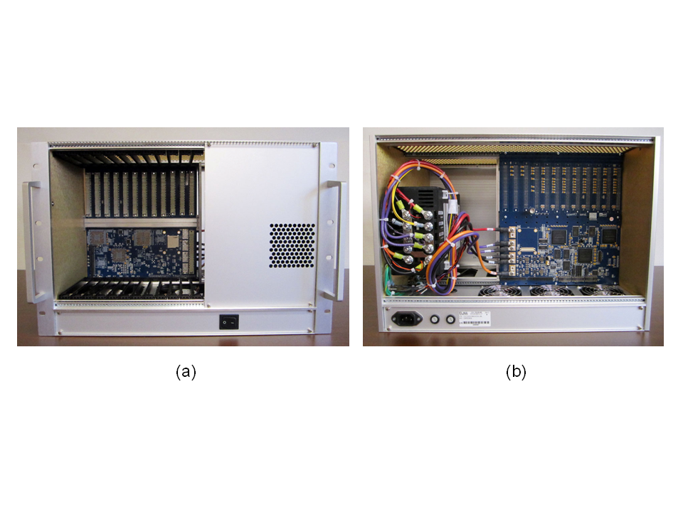
Fig. 12 The assembled OpenPET Support Crate viewed from the (a) front and (b) back.
Downloading the Software and Firmware
Installing QuickUSB
The OpenPET system requires the use of a QuickUSB module to provide high-speed USB 2.0 capability. You can purchase this online through Bitwise systems at http://www.bitwisesys.com/qusb2-p/qusb2.htm (product code QUSB2). In addition to the hardware module, this includes the QuickUSB library with a driver, interface DLL, and example programs for Linux, MacOSX and Windows. In addition, you will need a USB cable. However, you do not need to buy the QuickUSB Adapter Board as Bitwise implies.
First, you need to mount the QuickUSB module onto either the Host PC Interface Board in the U3 connector or onto the Support Board in the U6 connector (Fig. 13). The system is designed to work with the QuickUSB module mounted in either (but not both) of these locations.
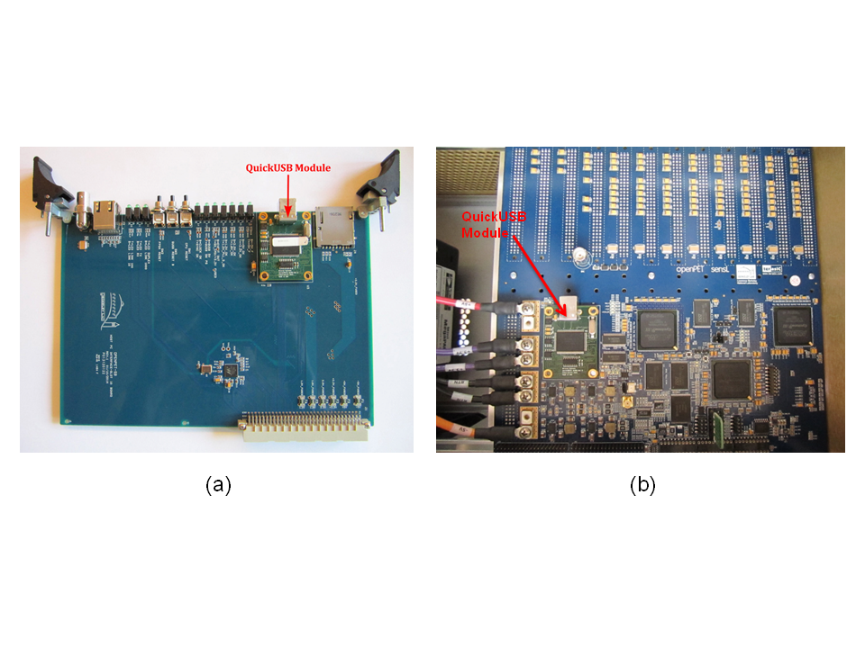
Fig. 13 QuickUSB module mounted onto the (a) Host PC Interface Board or (b) Support Board.
Next, you need to install the QuickUSB driver onto your Host PC. Browse and select the setup executable for the QuickUSB software (e.g., Desktop -> QuickUSB_Installation -> Windows -> setup.exe). This will launch the InstallShield Wizard in a new window (Fig. 14a). Step through the instructions by clicking the Next button at the bottom, agreeing to the software license agreement terms and defining the folder where the QuickUSB software should be installed (Fig. 14b). When the wizard is ready to begin installation of the library, click Install (Fig. 14c). The installation takes a few minutes and a status bar shows the progress. An additional window will then pop up that walks you through the installation of the QuickUSB device drivers (Fig. 14d). The InstallShield Wizard will indicate when the full installation is completed.
If you have further questions or problems with the installation, please refer to the Bitwise QuickUSB User Guide for details (e.g., http://www.bitwisesys.com/v/public/media/QuickUSB_User_Guide_v2.15.2.pdf).
Once you have installed the QuickUSB module, you need to confirm it has the correct firmware model. OpenPET uses the default firmware model i.e., “QuickUSB QUSB2 Module v2.15.2 (Simple I/O)”. If the version or the model is not correct, update the firmeware using the QuickUSB Programmer (see Fig. 15). After you have successfully installed the correct firmware, you can confirm your installation by running the QuickUsb Diagnostics (see Fig. 16). The OpenPET system requires the firmware model “QuickUSB QUSB2 Module v2.15.2 (Simple I/O)” to configure the QuickUSB module for the correct data transfer mode. For further details on this firmware model and configuration, please refer to the QuickUSB User Guide at http://www.bitwisesys.com/v/public/media/quickusb_user_guide.pdf.
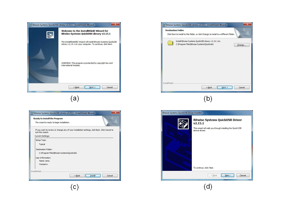
Fig. 14 Bitwise Systems QuickUSB Library v2.15.2 InstallShield Wizard: a) welcome window, (b) destination folder window, (c) installing the library window, and (d) installing the driver window.
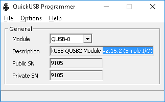
Fig. 15 QuickUSB Programmer used to program the QuickUSB module with the correct firmware: QuickUSB QUSB2 Module v2.15.2 (Simple I/O).
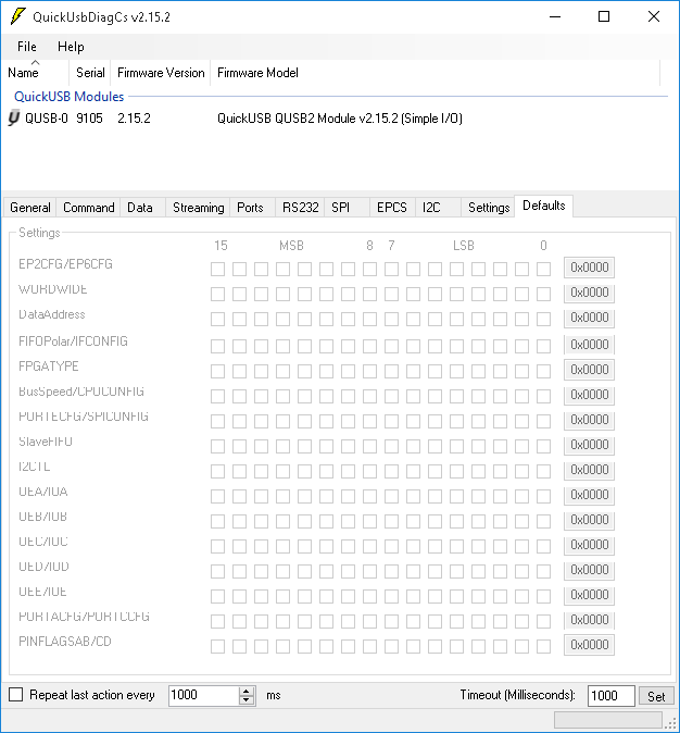
Fig. 16 QuickUsb Diagnostics used to confirm the QuickUSB module with the correct firmware: QuickUSB QUSB2 Module v2.15.2 (Simple I/O).
Installing Altera Tools
Even if you only plan to use the off the shelf OpenPET software and firmware, the OpenPET system requires the use of Altera design tools in order to load the appropriate firmware into the Support Board. These tools can be downloaded for free from the Altera Download Center website (e.g., https://www.altera.com/download/sw/dnl-sw-index.jsp, Fig. 17 a). From the Download Center, select to download the Quartus II Web Edition that is free and doesn’t require a license.
On the Quartus II Web Edition download page Fig. 17 b, select release: 13.1 select the Windows operating system and the Akamai DLM Download Manager. Under the Individual Files tab, select the Quartus II Software and the Cyclone III, Cyclone IV device support. You can select additional options (such as the ModelSim-Altera Edition simulation tools), but they are not required to run OpenPET and they will lengthen the download time.
At this time, only Altera Quartus 13.1 is supported.
You are then required to log in with your username and password if you already have a myAltera account. If not, then create an account using your email address and complete the account registration information. Once your myAltera account has been created, you will be directed to your myAltera Home page. Select the Download Center link on the top right side of the page.
Once you have returned to the Download Center (Fig. 17 a), select the Quartus II Web Edition and specify the Windows operating system, DLM Download Manager, Quartus II Software, and the Cyclone III, Cyclone IV device support (if they aren’t already specified). A separate Akamai NetSession Interface window will then pop up (Fig. 17 c) in which you should click Download on the installer and then Run to proceed with the software installation. You will have to agree to the End User License terms. A popup warning message will then appear in which you have to confirm that you want to open the executable file (e.g., QuartusSetupWeb-13.10.163.exe) from the Internet. You will then have to confirm that you want to allow this program to make changes to your computer (Fig. 17 d).
Finally the Quartus II Web Edition Setup Wizard window will appear and step you through the installation (Fig. 17 e). You will have to agree to a License Agreement again as well as specify the installation directory (e.g., C:altera13.1). Then you should make sure that the components selected for installation are correct (e.g., Quartus II Software and Cyclone III/IV) and that you have the available disk space specified in the Summary. Once you start the installation, a status bar will show its progress. Once the Setup has finished installing the Altera tools, you can create shortcuts on your Desktop and launch Quartus II (Fig. 17 f).
If you have further questions or problems with the installation, please refer to the Altera support website (http://www.altera.com/support/spt-index.html) for user information. For specific instructions on how to use these Altera tools with the OpenPET system, see Installing OpenPET Firmware & Software.
Installing USB-Blaster Driver
The USB-Blaster cable interfaces between a USB port on your Host PC and the Altera main FPGA on the Support Board. It allows configuration data to be sent from the Host PC to the FPGAs.
You must install the Altera USB-Blaster or USB-Blaster II driver before you can use the program devices with the Quartus II software. These drivers are automatically copied to the drivers folder within the Altera folder during the installation described in the previous section. However, it needs to be installed at first use. You will be prompted to install the driver the first time the USB-Blaster cable is plugged in. Whether you need to install the USB-Blaster or USB-Blaster II driver depends on your cable. Please see the step-by-step Altera instructions for this driver installation at http://www.altera.com/download/drivers/usb-blaster/dri-usb-blaster-vista.html.
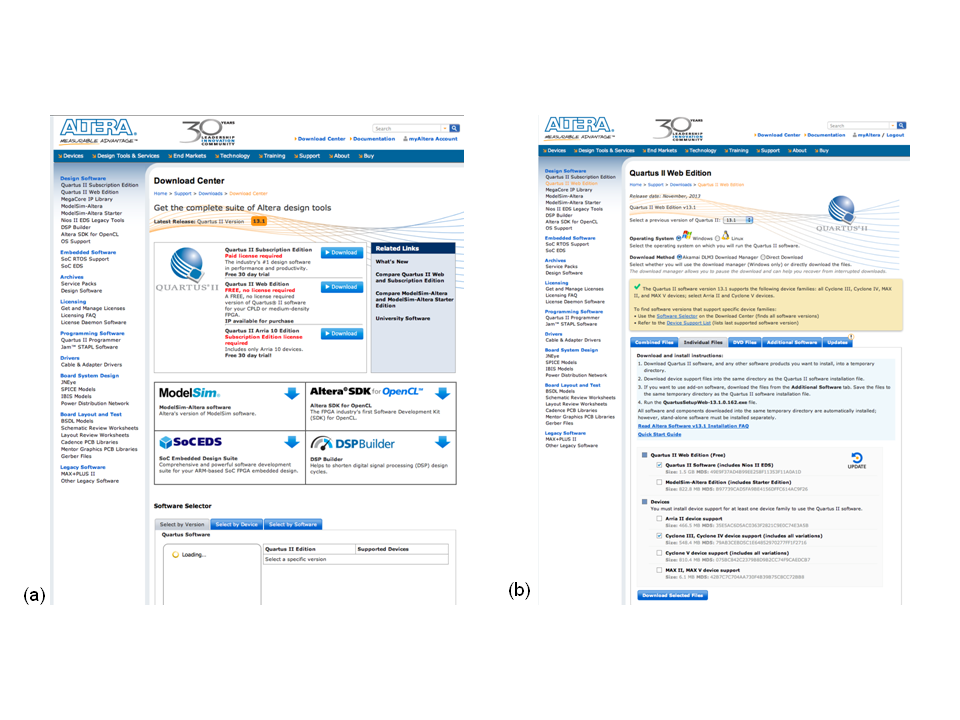
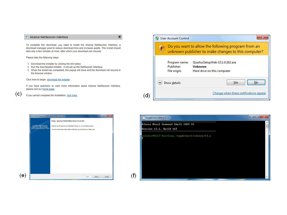
Fig. 17 Altera Tools installation windows: (a) download center window, (b) Quartus II Web Edition window, (c) Akamai NetSession Interface window, (d) User Account Control confirmation window, (e) Quartus II Web Edition Setup Wizard window and (f) Altera Nios2 Command Shell window.
Installing Ethernet
OpenPET also supports the capability of using Ethernet to configure and gather data from the system. You can connect your workstation to OpenPET Ethernet port on the HostPC Interface Board using a RJ45 cross-over cable or a (standard) straight-through cable with a switch in between. Both methods were tested. The network switch used was Netgear GS105.
To set up, open the Local Area Connection properties window for the connected Ethernet port (Fig. 18). Select Internet Protocol version 4.
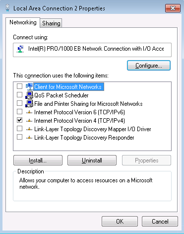
Fig. 18 Local Area Connection properties window with the desired TCP/IPv4 selected.
After selecting the correct protocol, click on the Properties button. The window shown in Fig. 19 will open. Here, the OpenPET IP address is set. Select “Use the following IP address” and copy the values shown for the IP address, Subnet mask, and Default gateway.
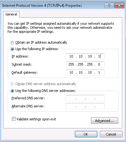
Fig. 19 Shows the IP address configuration for OpenPET
Next, click on the Advanced button and the Advanced TCP/IP Settings window will open. Navigate to the DNS tab and select the settings shown in Fig. 20.
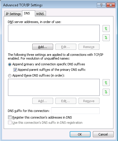
Fig. 20 Shows DNS settings
Also, disable NetBOIS over TCP/IP in the WINS tab as shown in Fig. 21.
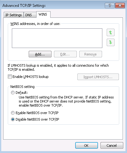
Fig. 21 Shows WINS settings
After the IP settings are done, if you would like to use Jumbo frames to increase the throughput of your ethernet, go back to the Local Area Connection properties window (Fig. 18). Click on the top right Configure button and navigate to the Advanced tab (Fig. 22). Select the Jumbo Packet property as shown and the correct value.
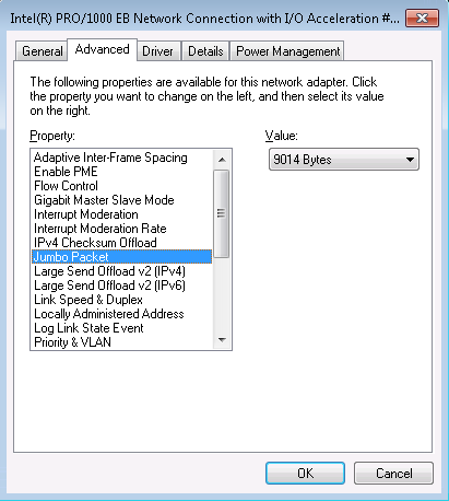
Fig. 22 Ethernet device configuration window
It might be desirable to to use static ARP in order to reduce unneeded broadcasts on your data acquisition port. Open a command line prompt with administrator privileges and type:
C:\> arp -s 10.10.10.2 12-55-55-00-01-28 10.10.10.1
where 10.10.10.2 is your destination IP (OpenPET Chassis), 12-55-55-00-01-28 is the MAC address of OpenPET HostPC PHY, and 10.10.10.1 is the IP address of your workstation.
Advanced Ethernet
In order to achieve high-performance GbE speeds, OpenPET recommends installing Netmap. Follow the README at https://github.com/luigirizzo/netmap.
Make sure your NIC is supported by netmap. Currently we are using 1GbE Ethernet Intel EXPI9301CTBLK
On FreeBSD 10.3:
cd /usr/src/sys/modules/netmap
# if you dont have the source, get it
#fetch ftp://ftp.freebsd.org/pub/FreeBSD/releases/amd64/X.X-RELEASE/src/txz
# X.X is version
#tar -C / -xvzf src.txz
make
kldload netmap
echo 'netmap_load="YES"' >> /boot/loader.conf

# setup NIC correct in rc.conf
# you need to disable lro, tso, etc.
# /etc/rc.conf e.g.:
ifconfig_em0="inet 10.10.10.1 netmask 255.255.255.0 mtu 9000"

# Allow openpet user to access netmap device
% cat /etc/devfs.conf
# allow openpet group to access netmap
# if you have a different username change openpet to something else
own netmap* root:openpet
perm netmap* 0660

# adjust netmap buffer size to accept jumbos
% cat /etc/sysctl.conf
sysctl dev.netmap.buf_size=9000
On Linux, change the IP as described above in for Windows and FreeBSD. Also, allow netmap to accept jumbo frames by changing the netmap_lin size to 9000:
echo 9000 > /sys/module/netmap_lin/parameters/buf_size
Installing OpenPET Firmware & Software
Download onto your Host PC the latest version of the OpenPET firmware and software “Binary” zip from the OpenPET website at http://openpet.lbl.gov/downloads/firmware-software/. You will need to register as an OpenPET user and login before you can access this page. Once you unzip this file (e.g., OpenPET_v2.0.zip), you should see the OpenPET_ROOTDIR directory, as shown in Fig. 23 .
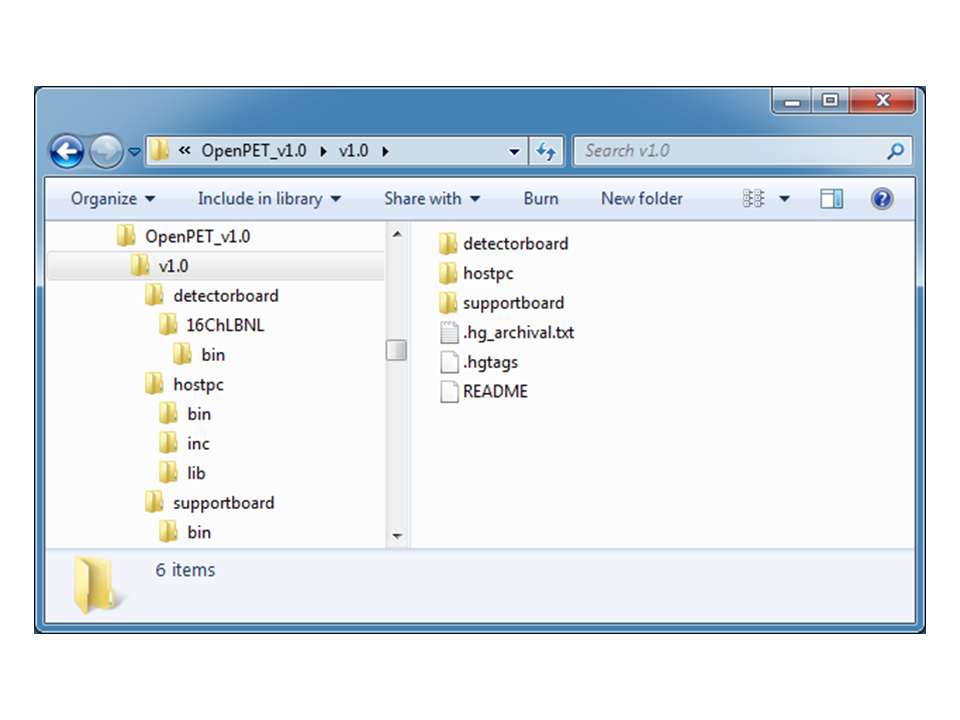
Fig. 23 OpenPET Directory Tree (OpenPET_ROOTDIR)
The directory ‘OpenPET_ROOTDIR/supportboard’ contains the Support Board’s firmware, as well as an additional script to program the board’s flash.
The directory ‘OpenPET_ROOTDIR/detectorboard’ contains the LBNL 16-channel Detector Board’s firmware and a script to program the flash. Future releases will also include other Detector Boards.
The directory ‘OpenPET_ROOTDIR/hostpc/dist/openpet’ contains the openpet.exe. This executable is a Microsoft Windows x64 executable for configuring the system and acquiring data. It is recommended that you add this directory to your MS Windows PATH environment variable. (You will have to do this every time a new OpenPET binary package is released.) Open a Windows Control Panel and type ‘env’ in the search box in the upper right corner as shown in Fig. 24 , then click on ‘Edit environment variables for your account’. When the new popup window appears, go to user variables, double click on the variable ‘PATH’, and append the full path to variable value (see Fig. 25 ).
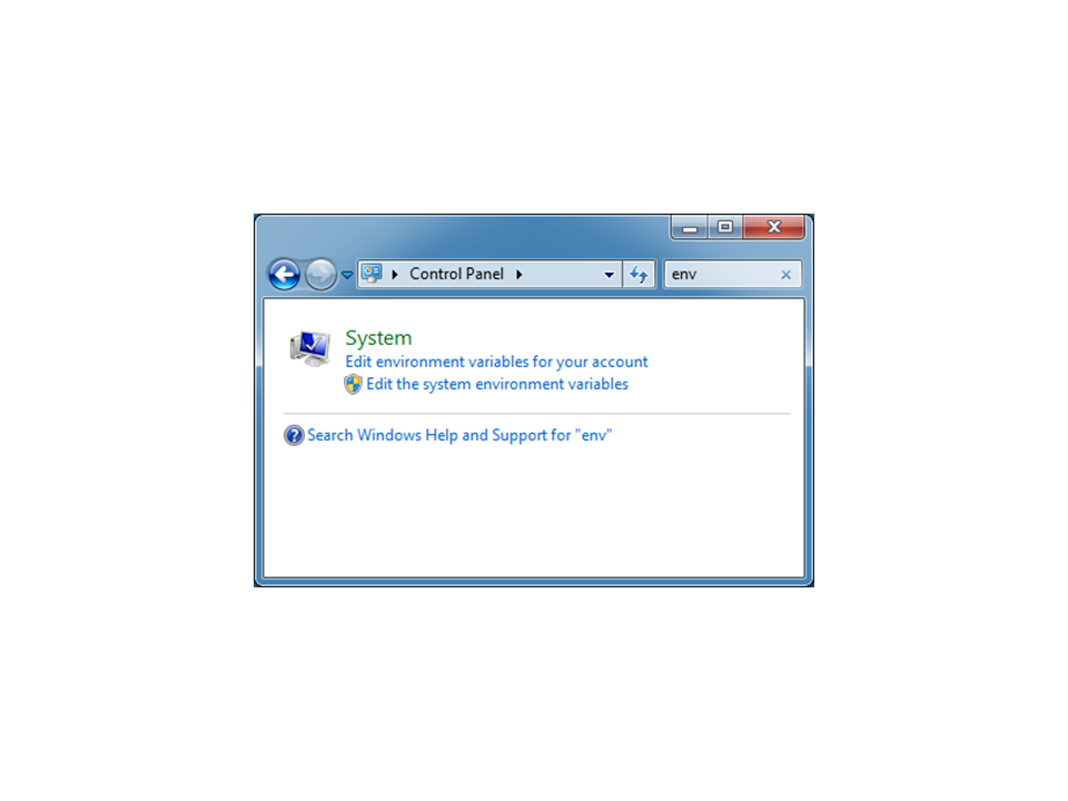
Fig. 24 Windows Environment Variable through control panel
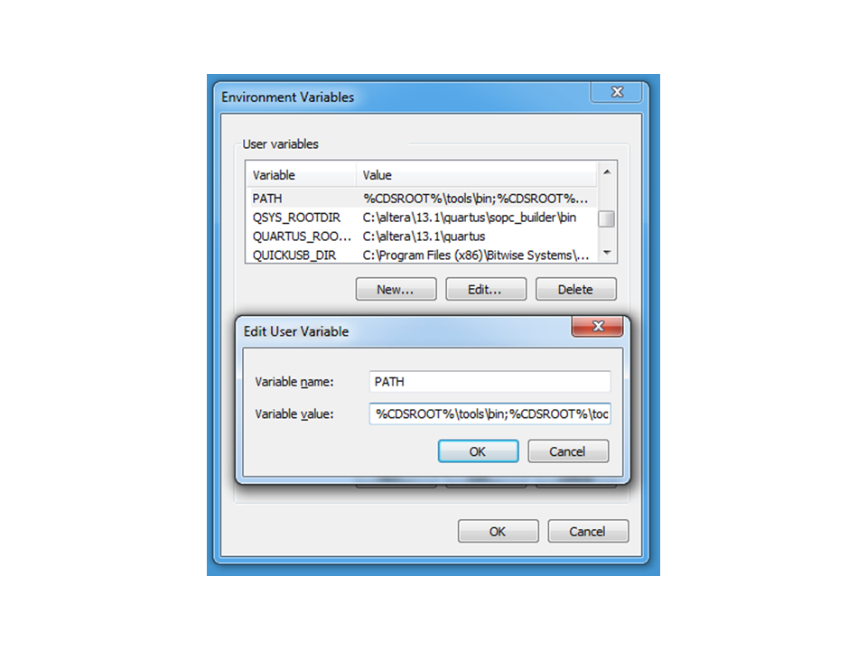
Fig. 25 Setting the PATH environment variable
Connecting USB-Blaster to Support Board
Before we program the flash images on the Support Board, we have to setup some jumpers. First make sure the Support Crate is powered off and disconnected. Place jumpers on each Detector Board, connecting pins 1 and 2 on J1, J2 and J3, so you can download firmware to the Detector Board (Fig. 26 (a)) using the instructions below. (Note: code can also be downloaded via the JTAG connector, which is still enabled with theses jumpers in place.)
Connect the USB-Blaster hardware from the back of the Support Board to your Host PC (USB port), as shown in Fig. 26 (b); pin 1 (marked as red) should face down when connecting to the JTAG connector.
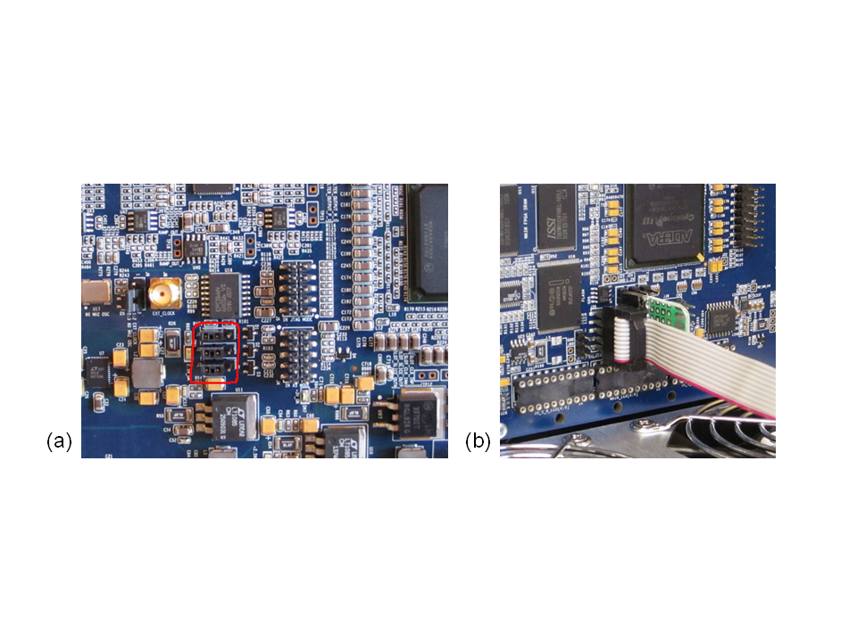
Fig. 26 (a) Detector Board with jumpers installed on pins 1 and 2 for J1, J2 and J3. (b) USB-Blaster plugged into the JTAG connector on the back of the Support Board. A custom jumper board is also shown.
Small System: Programming OpenPET Flash Images
After connecting the USB-Blaster cable, turn the power on to your Support Crate. Now you are ready to download the OpenPET software and firmware to your OpenPET hardware in two steps:
In the first step, you download the OpenPET software and firmware to the 3 FPGAs on the Support Board. In a Command Prompt window, change to directory OpenPET_ROOTDIR/supportboard and execute
flashboard.bat(on Microsoft Windows), orflashboard.shon GNU/Linux$ cd %OpenPET_ROOTDIR%\supportboard $ flashBoard.bat CDUC
The result is shown in Fig. 27. Once this is done, it is important that you reboot the crate by turning it off then on again.
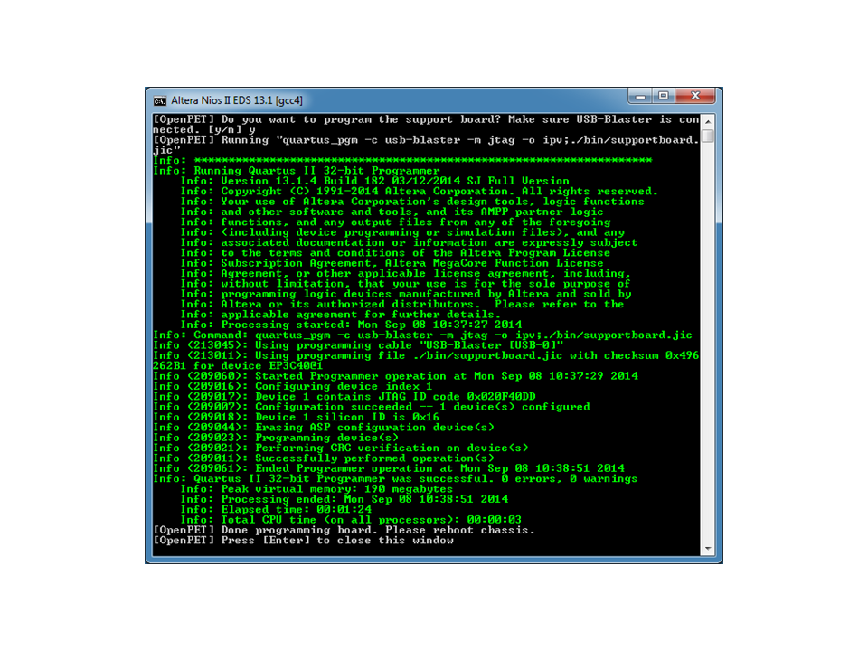
Fig. 27 Support Board flash programming script
In the second step, you download the OpenPET firmware to the Detector Board FPGA. In a Command Prompt window, change to directory OpenPET_ROOTDIR/detectorboard/16ChLBNL and execute
flashboard.bat(on Microsoft Windows), orflashboard.shon GNU/Linux:$ cd %OpenPET_ROOTDIR%\detectorboard $ flashBoard.bat
The result is shown in Fig. 28. When done, it is important that you reboot the crate by turning it off then on again.
Warning
You cannot program the detector board flash before programming the Support Board.
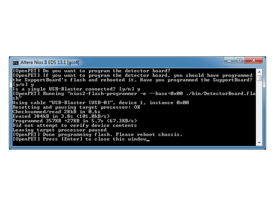
Fig. 28 Detector Board flash programming script
Standard System: Programming OpenPET Flash Images
Follow the following steps to flash the firmware on a Standard System:
First, you download the OpenPET software and firmware to the CU as shown in Fig. 5. Connect the USB_Blaster cable to the CU as described in Fig. 26 (b). In a Command Prompt window, change to directory OpenPET_ROOTDIR/supportboard and execute
flashboard.bat CUC(on Microsoft Windows), orflashboard.sh CUCon GNU/Linux:$ cd %OpenPET_ROOTDIR%\supportboard $ flashBoard.bat CUC
The result is shown in Fig. 27. Once this is done, it is important that you reboot the crate by turning it off then on again.
Second, you download the OpenPET software and firmware to each of the DU in your Standard System one at a time. Connect the USB_Blaster cable to a DU as described in Fig. 26 (b). In a Command Prompt window, change to directory OpenPET_ROOTDIR/supportboard and execute
flashboard.bat DUC(on Microsoft Windows), orflashboard.sh DUCon GNU/Linux:$ cd %OpenPET_ROOTDIR%\supportboard $ flashBoard.bat DUC
The result is shown in Fig. 27. Once this is done, it is important that you reboot the crate by turning it off then on again. Before you move to another DU, you download the OpenPET firmware to the Detector Board FPGA. In a Command Prompt window, change to directory OpenPET_ROOTDIR/16ChLBNL/detectorboard and execute flashboard.bat (on Microsoft Windows), or flashboard.sh on GNU/Linux:
$ cd %OpenPET_ROOTDIR%\detectorboard
$ flashBoard.bat
The result is shown in Fig. 28. When done, it is important that you reboot the crate by turning it off then on again.
- Third, repeat the previous step for all the DU in your Standard System.
Warning
When powering up a Standard System, always power up the CU first before the DUs.
Running OpenPET System
Any operating system (Windows, GNU/Linux, or Mac OS) and programmable language (C, C++, Delphi, MATLAB, VB.NET, and VC#) supported by QuickUSB can be used to interface with the OpenPET system. OpenPET provides multiple methods to control and configure the system. The simplest method is to use openpet.exe which is a Microsoft Windows executable that can configure and acquire data from an OpenPET system. Additionally, platform independent example Python scripts are also provided to streamline the configuration and acquisition process.
Prior to running the system with openpet.exe, you need to have the Small System hardware configured, powered on and loaded with the correct OpenPET firmware and software (see Assembling the Hardware and Downloading the Software and Firmware sections). You also need to plug in a QuickUSB cable to connect the Host PC (USB port) with either the Host PC Interface Board (plug into USB port on the front panel) or Support Board (plug into QuickUSB module directly on SB in back of crate).
Commands
OpenPET utilizes a standard 32-bit wide Serial Peripheral Interface (SPI) to facilitate serial communications between any parent node and its children. The communication protocol follows a request-response architecture, where a parent node writes a command to a child or multiple children then reads backs the response.
OpenPET commands are 80-bits wide as shown in Fig. 29. The first 16 most significant bits are the command id, followed by, source address (16 bits), destination address (16 bits), and payload (32 bits).

Fig. 29 OpenPET command (80-bits)
- Starting from the most significant bit (MSB):
- Command ID is defined below
- SRC/DST source/destination address is defined below
- Payload is defined per command (look in command folder)
The command id (Fig. 30) specifies the function of the command, using a 16-bit number. The most significant bit has two uses:
(a) used as a flag to denote a response/reply/acknowledgment from a node to its parent (direction=child-to-parent).(b) used as a flag to denote a non-blocking command i.e., asynchronous command (direction=parent-to-child).

Fig. 30 Command ID (16-bits)
Starting from the least significant bit (LSB):
(14:0) Command ID
(15)   Dual use flag
       (a) Child sets it to '1' when it responds to a parent
       (b) Parent sets it to '1' when it doesn't want to wait for the targeted child's
           response, i.e., non-blocking command or asynchronous command.
           Note: The targeted child will not reply to other commands if it is still
           busy executing this asynchronous command.
The source address is a 16-bit number that defines where the command originates. Typically, commands that originate at the Host PC have a source address of 0x4000. The destination address is a 16-bit number that identifies where the response should be received and processed. Both the source and destination addresses have the same address format, as shown in Fig. 31. The payload is a 32-bit number that specifies additional information/settings for each command. See Commands chapter for further details.
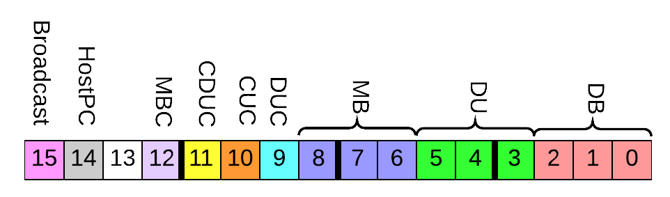
Fig. 31 Source/Destination address (16-bits)
Starting from least significant bit (LSB):
(2:0) Detector Board Address
(5:3) Detector Unit Address
(8:6) Multiplexer Board Address
(9)   Detector Unit Controller source/destination flag
(10)  Coincidence Unit Controller source/destination flag
(11)  Coincidence Detector Unit Controller source/destination flag
(12)  Multiplexer Board Controller source/destination flag
(13)  Not used
(14)  Host PC source/destination flag
(15)  Broadcast flag
The executable openpet is used to control and configure the system. It has several optional arguments, list them by running openpet with -h or --help switches.
The syntax of sending a command is:
$ openpet -c ID DST PAYLOAD
where ID is the command id, DST is the destination address, and PAYLOAD is the payload for that command. For example, to send a ping command to a detector board in slot 1:
$ openpet -c 0x0001 0x0001 0
It is possible to use decimal numbers instead of hex:
$ openpet -c 1 1 0
Tables 1 and 2 in Commands show the list of the current OpenPET commands available. See Commands for more details, including detailed examples.
Data Acquisition
The openpet executable is also used for acquiring data after the system has been correctly initialized. The syntax of sending this command is:
$ openpet -a DURATION -o FILENAME
where DURATION is the acquisition time in seconds or fractions of seconds and FILENAME is the output data file name. The content of the file will have the standard OpenPET data format. The -o switch is optional. If omitted openpet will then generate a unique file name called %Y%m%d-%H%M%S.openpetd, with the four digit year, then month, day, hour, minute, second.
Example System Setup & Data Acquisition of a Small System in Oscilloscope Mode
This section outlines an example of how to use the executables to initialize the system and take test data, in order to help determine whether your system is working properly. More information on diagnostic testing is also available in Appendix 2: Troubleshooting Diagnostics.
We list here an example string of commands – see Commands for more details on these commands. All of the commands below are sent through a the default QuickUSB module index, i.e., 0. On power-up the system configures all components to default values, see Appendix 1: Default Values for all default values.
The system must be properly programmed (see Connecting USB-Blaster to Support Board) before executing any of the commands below. Plug-in at least one detector board to the VME chassis and insert it in slot address 3 (this Detector Board will respond to any broadcast command with the destination address assigned to it in the example). Connect a pulse generator to any channel and set the amplitude to 600mV peak-to-peak and the frequency to 1 KHz. Now we will configure the OpenPET system.
Simple Example
Set the acquisition mode to scope. Note that the MSB in DST is set to 1 to denote broadcast to all nodes:
$ openpet -c 3 0x8007 0x00000001Set scope settings to 0x040F0201. Number of Samples is 32, samples before trigger is 15, and trigger window is 4:
$ openpet -c 5 0x8007 0x040F0201Acquire scope data for 10 seconds, save acquired data to
wave.openpetd$ openpet -a 10 -o wave.openpetd
The expected data should have a waveform similar to the one shown in Fig. 32.
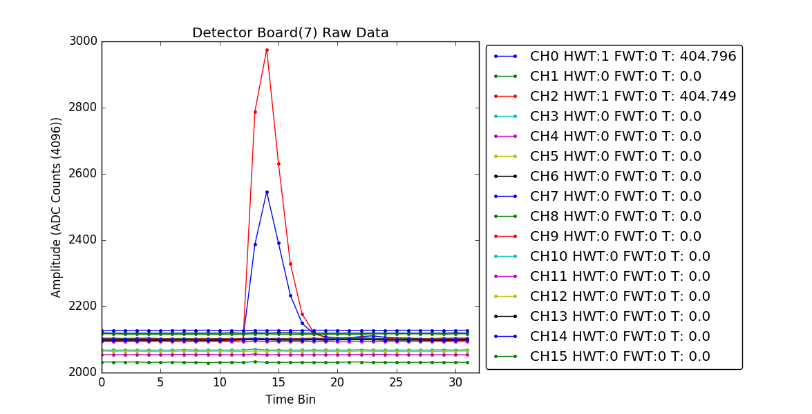
Fig. 32 Expected Waveform
Intermediate Example
The following example uses the high-resolution TDC, which is not the default TDC distributed in the version 2.0 firmware. In a later release, the user will be able to select the type of TDC through the command.
Set the Energy DAC threshold on all DBs to 400mV. Note that the MSB in DST is set to 1 to denote broadcast to all nodes:
$ openpet -c 0x0106 0x8003 0x8007E064Set the acquisition mode to scope. Note that the MSB in DST is set to 1 to denote broadcast to all nodes:
$ openpet -c 3 0x8003 0x00000001Set mode settings to 0x02000101. Number of Samples is 16, samples before trigger is 0, and trigger window is 2:
$ openpet -c 5 0x8003 0x02000100Set trigger mask to allow all channels to trigger
$ openpet -c 9 0x8003 0xFFFFFFFFReset high-resolution TDC
$ openpet -c 0x0101 0x8003 0x00000080Put high-resolution TDC in calibration mode
$ openpet -c 0x0101 0x8003 2Wait for 5 seconds, for high-resolution TDC to calibrate
$ timeout /t 5  (Microsoft Windows)
$ sleep 5       (UNIX/POSIX)
Put high-resolution TDC in normal mode
$ openpet -c 0x0101 0x8003 4Acquire scope data for 10 seconds, data will be saved in an autogenerated file name
$ openpet -a 10
Example System Setup & Data Acquisition of a Small System in Singles Mode
The same setup steps performed on scope mode still apply to Singles mode.
Simple Example
Set the acquisition mode to Singles. Note that the MSB in DST is set to 1 to denote broadcast to all nodes:
$ openpet -c 3 0x8007 0x00000002Set scope settings to 0x00010008. Integration length is 8, use 0xF-0x1=0xE=15 samples before trigger to average baseline:
$ openpet -c 5 0x8007 0x00010008Acquire scope data for 10 seconds, save acquired data to
sng.openpetd$ openpet -a 10 -o sng.openpetd
The expected data should have a waveform similar to the one shown in Fig. 33.
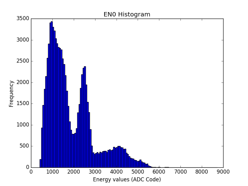
Fig. 33 Expected Singles Waveform
Data Analysis
Scope Mode
Scope mode data will be written to a binary file for further analysis and processing. The format for this data is specified in the following sections.
Users can also use an optional analysis tools package based on the ROOT framework, called OpenPET Control and Analysis Tools (OpenPET CAT). See OpenPET Control and Analysis Tools (OpenPET CAT) for further details on how to install and use OpenPET CAT.
Additionally, an example Python script is provided to plot scope mode data using matplotlib. Data acquired in Simple Example can be plotted by typing
$ python plot.py test.openpetd
Data Description and Arrangement
After running the system in scope mode, the DB(s) will periodically collect data until a channel triggers. Once a trigger is detected the raw data is passed from the DB(s) to the CDUC and then to the HostPC. If the CDUC FIFOs are full, the DB will inhibit all further triggers until the CDUC FIFOs can handle more data.
Packets in the data path are 32-bit wide. The four most significant bits are used to identify the packet. Packet id is used to verify packets received at a parent as well as identify, validate, and confirm the integrity of the packets in the data path. Below are the list of OpenPET packet ids:
0x0     Reserved
0x1     ADC Data
0x2     Reserved
0x3     Channel Header
0x4     DetectorBoard Header
0x5     DUC Header
0x6     CUC Header
0x7     CDUC Header
0x8     MBC Header
0x9     HostPC Header
0xA-F   Not Used
Single Detector Board
In scope mode, each DB outputs a block of data sequentially as shown in Fig. 34. The first packet of the data block is always the 32-bit DB header (depicted in Fig. 35) then a 32-bit channel header (shown in Fig. 36) along with its raw ADC data samples (shown in Fig. 37) then the next channel and its data and so on.
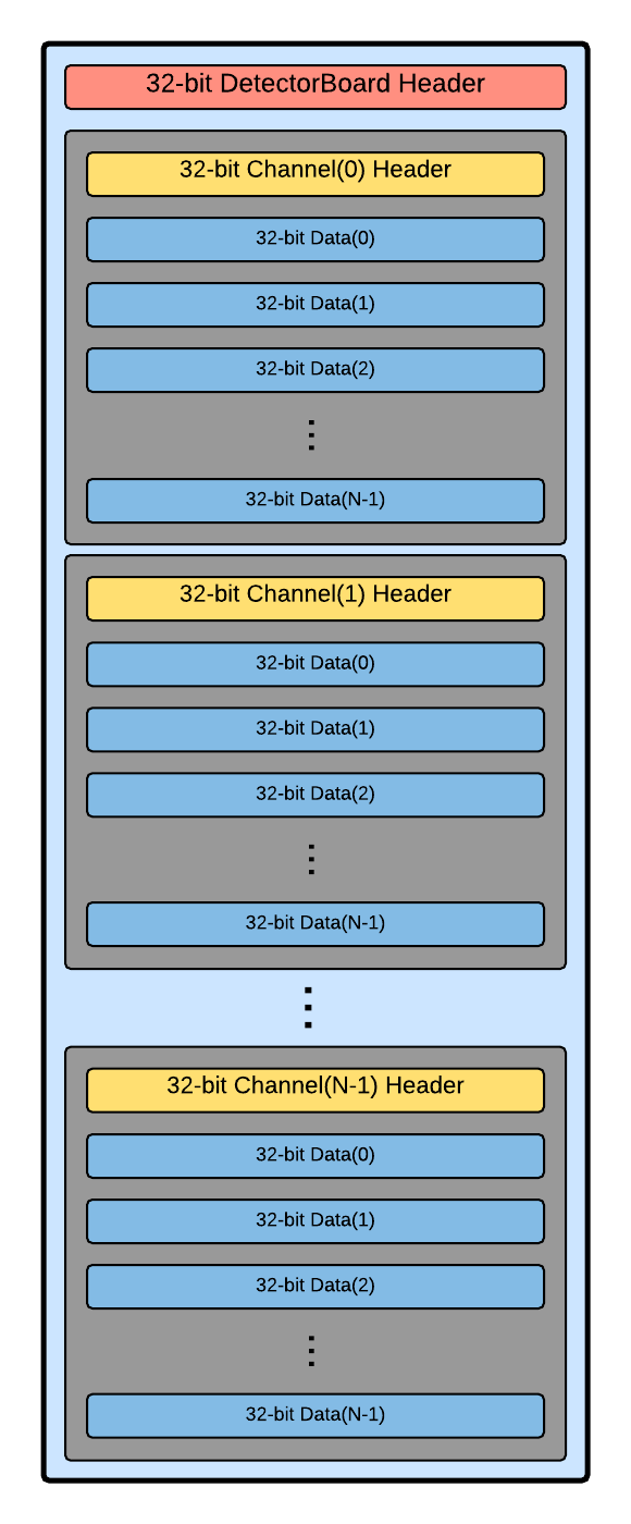
Fig. 34 DB Data Block in Scope Mode
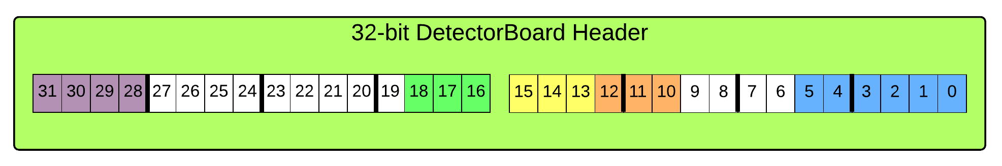
Fig. 35 32-bit DB Header
The 32-bit DB header contains the following information, starting from least significant bit (LSB):
(5:0)   Number of channel header packets (i.e. 0 to 63)
(9:6)   not used
(12:10) Detector Board Address (populated by parent)
(15:13) DU Address (populated by parent)
(18:16) MB Address (populated by parent)
(27:19) not used
(31:28) Packet ID (must equal to 0x4)
* More bits are used for future expansions.
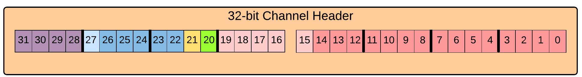
Fig. 36 32-bit Channel Header
The 32-bit DB header contains the following information, starting from least significant bit (LSB):
(19:0)  TDC data (if used) (9:0) is fine count, the rest is coarse.
(20)    Hardware trigger hit (energy)
(21)    Firmware trigger hit
(27:22) Channel address (i.e. 0 to 63)
(31:28) Packet ID (must equal to 0x3)
* More bits are used for future expansions.
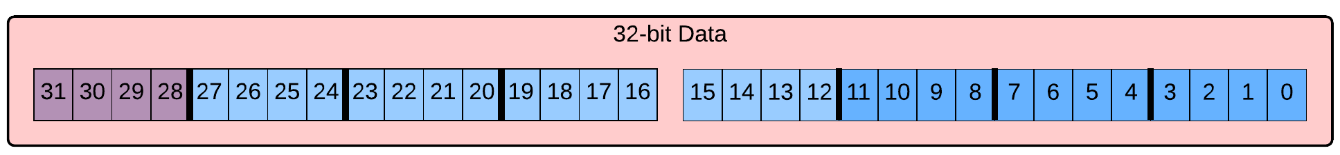
Fig. 37 Raw ADC Sample
The 32-bit raw ADC sample contains the following information, starting from least significant bit (LSB):
(27:0)  Raw ADC data. Currently (11:0) is utilized.
(31:28) Packet ID (must equal to 0x1)
* More bits are used for future expansions.
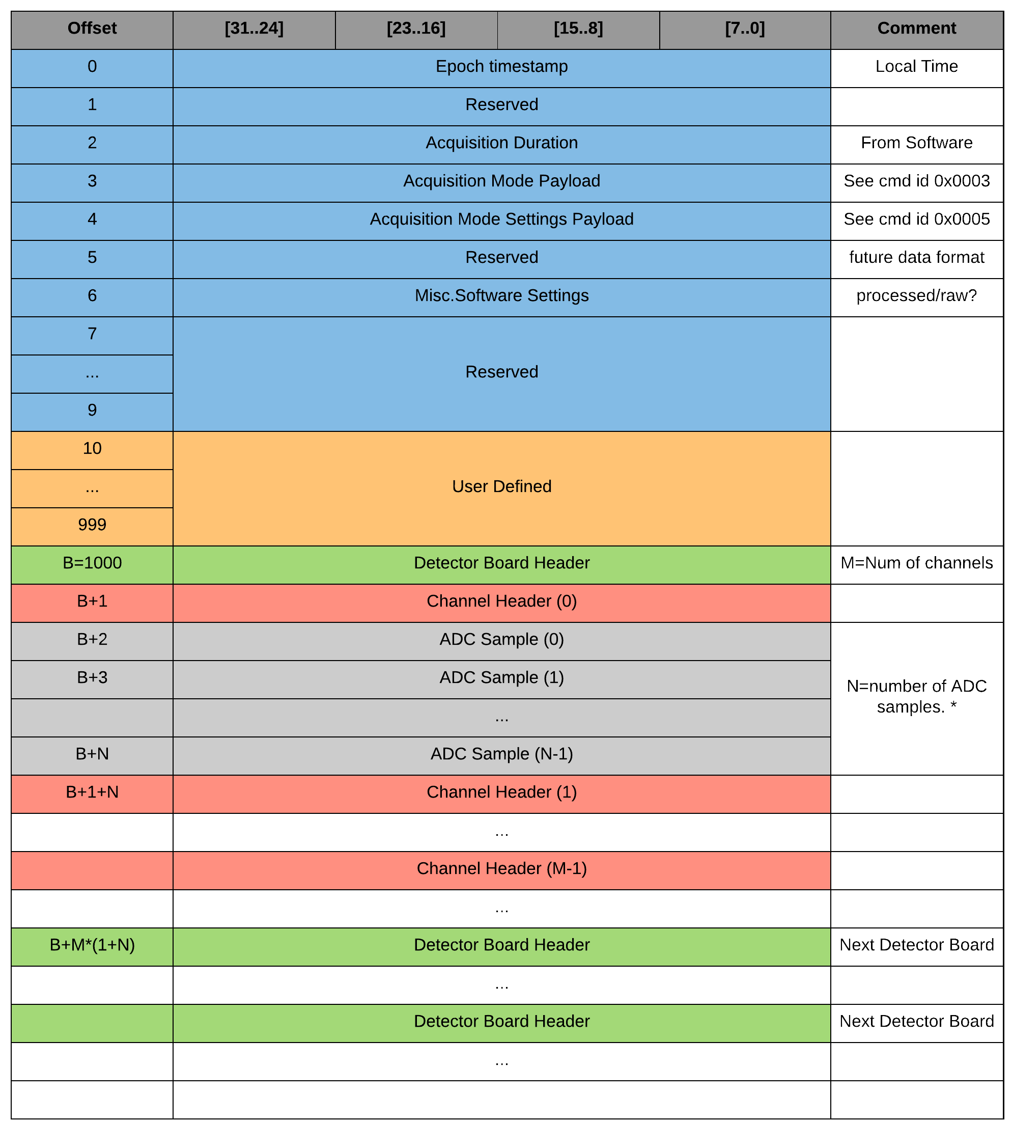
Fig. 38 Scope Mode binary file format.
The data is prepended with a header as shown in Fig. 38. All the settings including the acquisition time are stored in the header.
Multiple Detector Boards
In scope mode, a detector board will output its data whenever a trigger occurs. In other words, the IO FPGA doesn’t arrange or sort detector board data coming from multiple boards. Data blocks are passed to the Main FPGA based on first-come-first-serve scheme. Fairness is preserved by using a one-dimensional queue with a depth of 8 for each IO FPGAs and 4 for Main FPGA. The first data block data entires the queue, will be send to the main FPGA first.
Singles Mode
Singles mode data will be written to a binary file for further analysis and processing. The format for this data is specified in the following sections.
Users can also use an optional analysis tools package based on the ROOT framework, called OpenPET Control and Analysis Tools (OpenPET CAT). See OpenPET Control and Analysis Tools (OpenPET CAT) for further details on how to install and use OpenPET CAT.
Additionally, an example Python script is provided to plot scope mode data using matplotlib. Data acquired in Simple Example can be plotted by typing
$ python plot_singles_energy.py test.openpetd
Data Description and Arrangement
Singles mode uses slices to divide acquisition time to predefined time bins. First, let’s define some constants. The slice width N is calculated as R times the slice period divided by the system clock period where R is the system clock period divided by the ADC clock period.

Fig. 39 Singles mode frame definition
Example 1:
Default System Clock Period = 12.5ns (80MHz)
Default ADC Clock Period = 25ns (40MHz)
Slice period = 100ns (10MHz)
R = 12.5/25 = 1/2
N = 1/2 * 100/12.5 = 4 packets
Total bits transferred per slice = 4 * 32 = 128 bits
Example 2:
Default System Clock Period = 12.5ns (80MHz)
Default ADC Clock Period = 25ns (40MHz)
Slice period = 200ns (5MHz)
R = 12.5/25 = 1/2
N = 1/2 * 100/12.5 = 8 packets
Total bits transferred per slice = 8 * 32 = 256 bits
Note
N should be an integer. Use ceil() to round to the nearest integer toward infinity.
Fig. 40 is an example for N = 4 and for a specific event processing where the energies of the first four channels in 16-channel DB are calculated by integrating a fix number of samples of the signal waveforms. 8-bit TDC values are inserted to correlate the events in time.
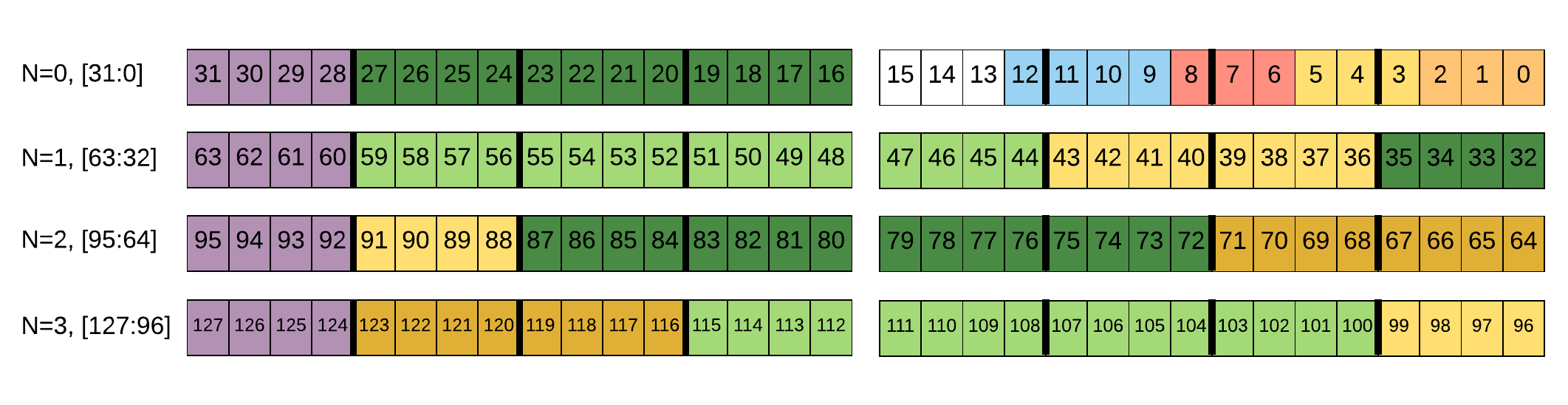
Fig. 40 Example when slide width equals 4.
Starting from least significant bit (LSB)
(2:0) Detector Board Address (populated by parent)
(5:3) DU Address (populated by parent)
(8:6) MB Address (populated by parent)
(12:9) Number of channels that triggered
(15:13) Unused
(27:16) Channel0 16-bit Energy -- four bits continued after packet ID
(31:28) Packet ID
(35:32) Continuation Channel0 16-bit Energy
(43:36) Channel0 8-bit TDC
...
(115:100) Channel3 16-bit Energy
(123:116) Channel3 8-bit TDC
(127:124) Packet ID
For a given 32-bit packet, the packet ID is the most significant four bits. Packet IDs are used to verify packets received at a parent. It also allows a node to identify, validate, and semi-confirm the integrity of the packet in the data path.
Fig. 41 Example of packet ID payload
Below are the list of singles mode packet IDs:
0x0           Reserved. DO NOT USE
0x1-0x4       Singles Packet sequence number. i.e., N+1
0x5-0xF       Not used
In singles mode, the data file format is as shown in Fig. 42.
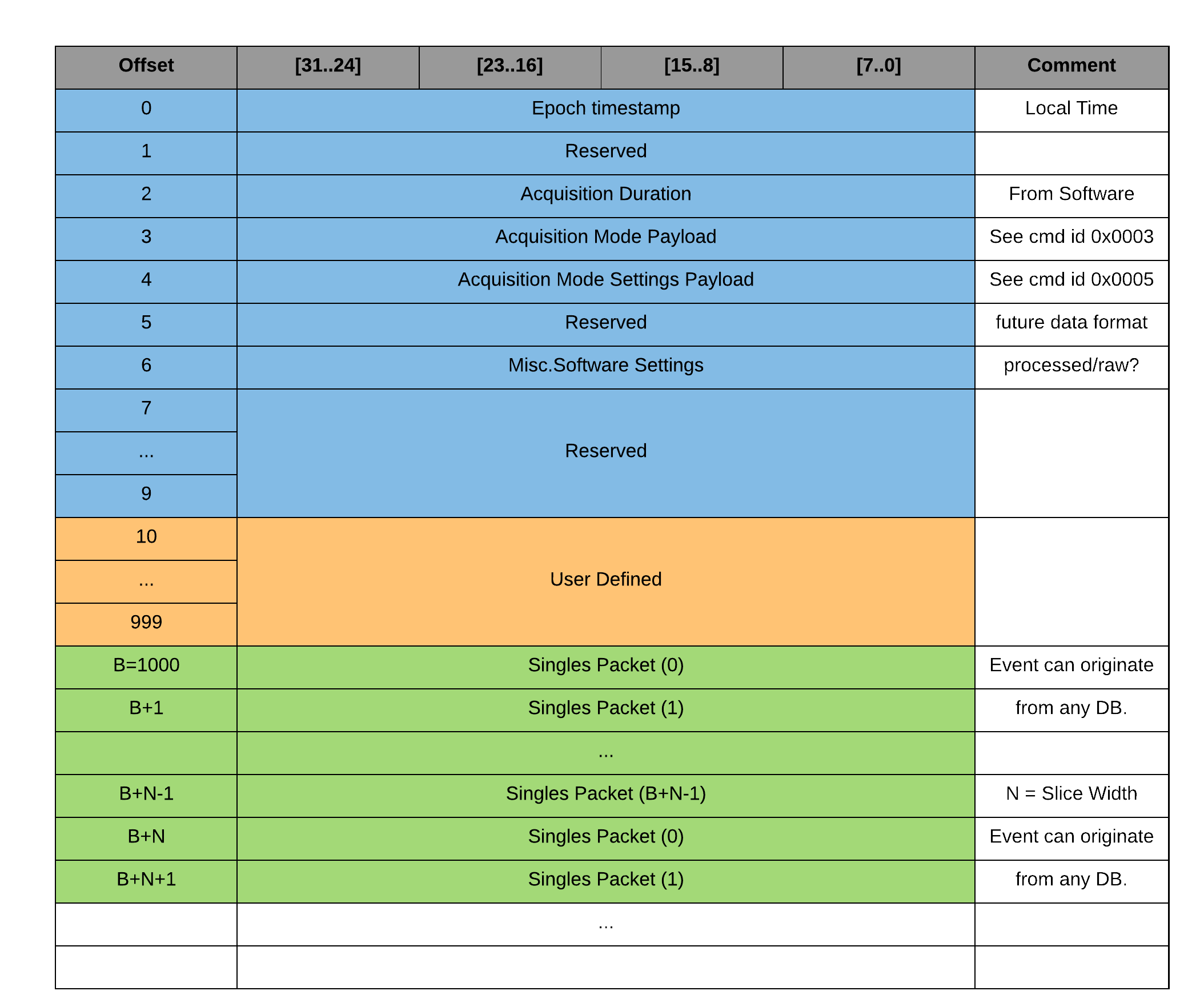
Fig. 42 Singles Mode binary file format
The payload for writing the system acquisition settings in singles mode is given in Fig. 43.

Fig. 43 System Acquisition Mode Settings payload for singles mode
Starting from least significant bit (LSB)
(3:0) Number of samples to integrate, i.e., integration length (Defined as A in figure below)
(7:4) Reserved
(15:8) Reserved
(19:16) Integration starting point (Defined as B in figure below)
(31:24) Not Used
Note
- Number of pipeline stages is pre-defined in the firmware as a constant
- PipelineStages = ceil(EventCompuationClockTicks/SliceWidth) + 1 , where ceil() rounds the number to the next highest integer.
- The trigger location is always set at time bin = 16 in the firmware. In other words, the number of samples before the energy trigger are always 16.
- Baseline is computed as the moving average of samples located between [0 to 16-B] as shown in Fig. 44.
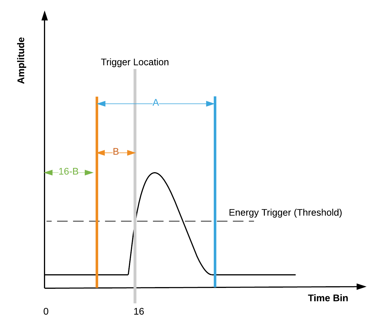
Fig. 44 Acquisition mode settings payload mapping.
Example:
Let A = 9 and B=1
ADC values from [0 to 15] will be averaged to create the baseline values to be removed from all consecutive samples.
ADC values from [16 to 24] will be integrated (summed)
Getting Help
The goal of OpenPET is to create an active community of general users and developers, so that we can all pool our resources and expertise. In order to help build this OpenPET support network, we have created an opt-in email list for people that want to keep informed of OpenPET news and updates. You can add your email to this OpenPET email list by sending a message to sympa@lists.lbl.gov with the subject line “subscribe openpet-users@lbl.gov”.
For general questions, please see the documentation available on the OpenPET website, including presentations, publications and user guides (http://openpet.lbl.gov/documentation/general-documents). You can also check the website’s Frequently Asked Questions at http://openpet.lbl.gov/users/faq/.
If you have specific questions, you can read and post questions using the OpenPET forums on our website at http://openpet.lbl.gov/forums/. Please check past discussion threads before creating a new one.